
Short Answer
Key Formula / Key Facts Box
Core formula for inside diameter (ID):
ID = OD – 2·WT
| Symbol | Meaning | US Unit | SI Unit | Plain‑English Restatement |
|---|---|---|---|---|
| OD | Outside diameter of the pipe | inches (in) | millimetres (mm) | The total width of the pipe measured across its outer wall. |
| WT | Wall thickness (schedule‑defined) | inches (in) | millimetres (mm) | The thickness of the pipe wall on one side. |
| ID | Inside diameter (flow area) | inches (in) | millimetres (mm) | The clear aperture through which fluid travels. |
| NPS | Nominal Pipe Size (designation only) | inches (in) | millimetres (mm) | A convenient label that approximates the pipe’s ID for standard schedules. |
Overview — What It Is and Why It Matters
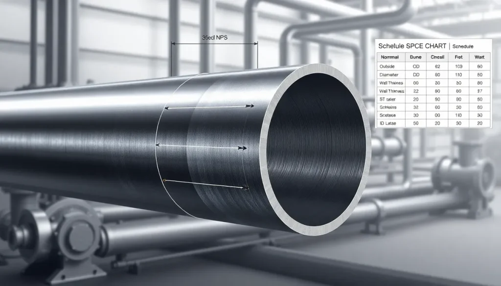
The term “steel pipe schedule” is a legacy from the American National Standards Institute (ANSI) that links a pipe’s nominal size to a prescribed wall thickness. The schedule number (e.g., Schedule 40, Schedule 80) does not represent a physical dimension; instead it encodes a pressure class that engineers use to size piping for pumps, compressors, and process equipment. By consulting a schedule chart, designers instantly obtain the outside diameter (OD), wall thickness (WT), and derived inside diameter (ID)—the latter directly governs flow area, velocity, Reynolds number, and ultimately pump head and power requirements.
Errors in interpreting the chart lead to mis‑selected pipe sizes, causing excess pressure drop, vibration, or catastrophic failure under design pressure. Because pump performance curves are highly sensitive to flow area, a 5 % underestimate of ID can inflate required pump horsepower by 10 % or more.
The Method — Derivation and Variants
Standard pipe dimensions are defined by ASME B36.10 (seamless and welded carbon steel) and ASME B36.19 (stainless steel). The derivation follows a simple geometric relationship:
ID = OD – 2·WT
where OD is a fixed value for a given nominal size (NPS). WT is selected according to the schedule, which is itself a function of the allowable stress, design temperature, and design pressure (per ASME B31.3). Two common variants exist:
- US‑customary form: OD and WT are tabulated in inches; the schedule number is an integer (e.g., 10, 40, 80).
- SI form: The same values are presented in millimetres; many European codes replace the schedule with a “PN” (pressure class) designation, but the underlying geometry is identical.
When converting between systems, the conversion factor 1 in = 25.4 mm is applied to both OD and WT before recomputing ID.
Worked Example
Example 1 – US customary units
- Design calls for a 2‑in nominal pipe (NPS 2) carrying water at 150 psi.
- From ASME B36.10, Schedule 40 OD = 2.375 in, WT = 0.154 in.
- Compute ID: ID = 2.375 in – 2·0.154 in = 2.067 in.
- Convert ID to cross‑sectional area: A = π·(ID/2)² = 3.1416·(1.0335)² ≈ 3.36 in².
- Using the Darcy‑Weisbach equation, the pressure drop for the given flow is calculated; the result verifies that the pipe meets the allowable 10 psi loss.
Example 2 – SI units
- Same design, but the engineer prefers millimetres. NPS 2 corresponds to OD = 60.33 mm.
- Schedule 40 wall thickness = 3.91 mm.
- ID = 60.33 mm – 2·3.91 mm = 52.51 mm.
- Area = π·(52.51/2)² ≈ 2166 mm² = 3.36 in² (consistent with Example 1).
- Proceed with the same head loss calculation using metric fluid properties.
Calculator
For rapid conversion and validation, use an online pipe‑dimension calculator such as Engineering Toolbox Pipe Dimensions Calculator.
Reference Values & Typical Ranges
| Nominal Size (NPS) | OD (in) | Schedule 40 WT (in) | ID (in) | Schedule 80 WT (in) | ID (in) – Schedule 80 |
|---|---|---|---|---|---|
| ½ | 0.84 | 0.083 | 0.674 | 0.147 | 0.546 |
| 1 | 1.315 | 0.133 | 1.049 | 0.179 | 0.957 |
| 2 | 2.375 | 0.154 | 2.067 | 0.218 | 1.939 |
| 4 | 4.500 | 0.237 | 4.026 | 0.337 | 3.826 |
| 6 | 6.625 | 0.300 | 6.025 | 0.432 | 5.761 |
Typical pressure ratings (per schedule) for carbon‑steel pipe at 20 °C:
- Schedule 40 – 2 in: ≈ 280 psi (≈ 19 bar)
- Schedule 80 – 2 in: ≈ 560 psi (≈ 38 bar)
- Schedule 120 – 2 in: ≈ 740 psi (≈ 51 bar)
Application Guidance
When selecting pipe for a pump‑circulation loop, follow these steps:
- Determine the design pressure and temperature; consult ASME B31.3 to select a schedule that meets or exceeds the required pressure class.
- Calculate the required flow area from the pump’s curve (Q = A·v). Choose the smallest nominal size whose ID (derived from the schedule) yields a velocity ≤ 8 ft/s for liquids or ≤ 20 ft/s for gases.
- Check corrosion allowance: add extra thickness (commonly 1/8 in or 3 mm) to the schedule‑specified WT for aggressive media.
- Verify that the selected pipe’s OD fits within the available fittings, supports, and clearances.
- Apply a safety factor of 1.25–1.5 on the pressure rating when the system will experience frequent pressure spikes (e.g., pump start‑up).
Field‑judgment adjustments often involve “up‑scheduling” (choosing a heavier schedule) when weld quality cannot be guaranteed or when the pipe will be buried underground, where external loads increase.
Common Mistakes, Limits & Safety Notes
- Confusing nominal size with ID. NPS is a label; the actual ID varies with schedule. Always compute ID from the chart.
- Mixing US and SI units. Applying an inch‑based WT to a millimetre OD (or vice‑versa) yields nonsensical IDs.
- Neglecting corrosion allowance. Using the nominal schedule thickness for corrosive fluids can lead to premature wall‑thinning and failure.
- Assuming schedule number equals pressure. Schedule 40 on a 2‑in pipe does not equal 40 psi; consult the pressure‑rating table.
- Overlooking temperature derating. Steel strength drops with temperature; the allowable pressure for a given schedule must be reduced per ASME B31.3 tables.
- Using the chart beyond its intended range. Very large NPS values (> 24 in) or non‑standard alloys require proprietary data sheets, not the generic schedule chart.
- Ignoring weld‑joint efficiency. For welded pipe, the design pressure must be multiplied by the joint efficiency factor (E) before selecting a schedule.
- Safety consequence: Undersized wall thickness can cause burst under pressure, leading to equipment damage, personnel injury, and environmental release.
FAQ
What does the schedule number actually represent?
The schedule number is a shorthand for a wall‑thickness class defined by ASME. It does not equal pressure; instead, it correlates to a pressure rating that varies with pipe size, material, temperature, and design code.
Can I use the same schedule for stainless‑steel pipe?
Stainless‑steel dimensions follow ASME B36.19, which uses the same nominal sizes and schedule numbers, but the pressure ratings differ because stainless steel has different allowable stresses.
How do I convert a schedule chart from inches to millimetres?
Multiply both OD and WT values by 25.4 mm/in to obtain metric dimensions, then recompute ID using the same ID = OD – 2·WT relationship.
Is Schedule 40 always the lightest pipe I can use?
For a given nominal size, Schedule 40 has the smallest wall thickness among the common schedules. However, for very small NPS values, Schedule 5S may be lighter, and for high‑pressure service a heavier schedule is required.
Why does the inside diameter change with schedule?
Because the wall thickness increases with higher schedules, the ID shrinks according to ID = OD – 2·WT. A larger wall thickness reduces flow area and raises velocity for a given flow rate.
Do pipe dimensions change with temperature?
Thermal expansion changes the OD slightly, but the schedule chart assumes dimensions at 20 °C. Design codes provide temperature derating factors for pressure, not for geometry.


Leave a Reply