Short Answer
Key Formula / Key Facts Box
No single closed-form formula predicts elbow-induced distortion in a double-suction pump. The effect depends on elbow geometry, spacing, Reynolds number, upstream fittings, and pump inlet geometry. Use the diagnostic flow-split index below for field evaluation, and use CFD or manufacturer testing for design decisions.
Diagnostic flow-split index: φ = (Qout − Qin) / Qtotal × 100%
| Symbol | Meaning | US unit | SI unit |
|---|---|---|---|
| φ | Flow-split imbalance index | % | % |
| Qout | Flow to the favored or outboard eye | gpm | m³/h |
| Qin | Flow to the opposite or inboard eye | gpm | m³/h |
| Qtotal | Total pump suction flow | gpm | m³/h |
Plain-English restatement: φ tells how much more flow one impeller eye receives than the other as a percentage of total pump flow; zero means a balanced split.
| Key fact | Practical value |
|---|---|
| Common straight-run recommendation | About 5 to 10 pipe diameters upstream of the pump inlet, depending on standard, elbow type, and manufacturer requirements. |
| Typical closed-system suction velocity limit | Often ≤8 ft/s (≤2.4 m/s) at design, per Hydraulic Institute guidance cited by Deppmann. |
| Main distortion mechanism | Bend-induced pressure gradient, separation, and counter-rotating secondary vortices create a skewed and swirling inlet profile. |
| Double-suction consequence | Uneven flow to the two impeller eyes can degrade head and efficiency, promote cavitation, and disturb axial thrust balance. |
| Typical mitigation | Long-radius elbow, additional straight run, suction diffuser, flow conditioner, multiple-vane compact elbow, or acceleration elbow. |
Overview — What It Is and Why It Matters
This article uses the common encyclopedic meaning of suction elbow distortion: a 90-degree bend, often close-coupled to the suction flange of a horizontal double-suction centrifugal pump, that produces a non-uniform velocity profile entering the pump. It does not cover intake elbows for large vertical tubular-casing pumps except where the same flow-physics principles apply. The focus is the layout problem seen in process, HVAC, water, and industrial pump installations where space limits straight suction piping.

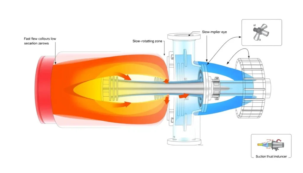
A double-suction impeller is designed to draw liquid from both sides, or eyes, of the impeller. When the two inlet streams are equal and well distributed, the hydraulic forces on the impeller are approximately balanced and the pump can operate near its factory-tested curve. A suction elbow disrupts that assumption. As liquid turns through the bend, centrifugal effects and pressure gradients create faster flow near the outer wall, separation near the inner wall and downstream regions, and a pair of counter-rotating vortices. The result is a distorted, swirling velocity profile that persists for several pipe diameters downstream.
When that profile reaches a double-suction pump, the inlet passage splits the flow toward two impeller eyes. One eye may receive a higher velocity and greater share of the flow, while the other receives less. The pump no longer sees the symmetrical inlet condition assumed by its axial-thrust balance. Field symptoms can include reduced head and efficiency, cavitation, noise, vibration, bearing temperature rise, seal distress, impeller erosion, and premature failure. Kriebel describes exactly this failure pattern for a horizontal elbow immediately before a double-suction pump: uneven distribution to the two impeller eyes, flow instability, cavitation, and loss of axial thrust balance.
The problem matters because real plants rarely provide ideal suction piping. Metraflex notes that manufacturers commonly recommend about 10 diameters of straight pipe upstream of a pump inlet, yet space and equipment layout often force a close-coupled elbow. Vortab reports that pump manufacturers may recommend 3 to 10 diameters, while Deppmann notes that a common rule of thumb is five diameters or a suction diffuser. These are minimum-practice guides, not guarantees. A double-suction pump does not automatically cancel swirl; a poorly placed elbow can make the two-eye inlet condition worse.
The Method — Derivation and Variants
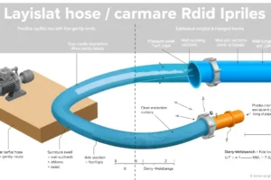
The physics starts with the radial momentum balance in a bend. A fluid particle following a curved path needs centripetal acceleration approximately equal to V²/R, where V is local velocity and R is the bend centerline radius. This is provided by a radial pressure gradient, roughly dp/dr ≈ ρV²/R. Because the pressure field, upstream inertia, and wall separation interact, the velocity profile leaving the bend is not uniform. Separation can occur near the outer wall due to the adverse pressure gradient and near the inner wall due to the sharp turn. The remaining core flow accelerates, and secondary flows form. The classic result is a pair of counter-rotating vortices, often called Dean vortices, superimposed on the main flow.
A useful dimensionless indicator is the Dean number, which combines Reynolds number with curvature ratio. In US customary and SI forms the expression is the same because both groups are dimensionless:
US customary: De = (V D / ν) × √(D / 2R), with V in ft/s, D in ft, R in ft, and ν in ft²/s.
SI: De = (V D / ν) × √(D / 2R), with V in m/s, D in m, R in m, and ν in m²/s.
Here D is the pipe inside diameter, R is the bend centerline radius, V is bulk velocity, and ν is kinematic viscosity. Higher Dean number indicates stronger secondary flow for a given bend. The curvature ratio R/D distinguishes a short-radius elbow from a long-radius elbow: a short-radius elbow commonly has R/D near 1.0, while a long-radius elbow is often near 1.5. The distortion decays downstream by turbulent mixing, but the required length is not captured by a simple universal equation and depends strongly on upstream disturbances and pump inlet geometry.
For double-suction pumps, the critical variant is elbow orientation relative to the impeller split. An elbow in a plane that feeds one eye preferentially can create a persistent flow bias; a different orientation may create a more symmetric but still swirling profile. KSB notes that standard constant-section intake elbows cannot ensure disturbance-free flow and that double-entry single-stage pumps fitted with standard elbows can suffer efficiency loss, cavitation, and impaired smooth running because each half of the impeller receives a different flow. Mitigation variants include long-radius elbows, reducing elbows, compact elbows with multiple deflection vanes, acceleration elbows that increase velocity through the bend, suction diffusers, and elbow flow conditioners. Each has limits: flow conditioners add pressure drop, long-radius elbows still require space, and multiple-vane designs must be selected for the actual flow range.
Worked Example
US customary example. A horizontal split-case double-suction pump handles Qtotal = 2000 gpm through a 12 in suction line with a short-radius 90-degree elbow directly at the flange. Assume water at about 68°F, ν = 1.08 × 10⁻⁵ ft²/s, D = 1.0 ft, and R/D = 1.0. First calculate area: A = πD²/4 = π(1.0)²/4 = 0.7854 ft². Convert flow: 2000 gpm ÷ 448.831 = 4.456 ft³/s. Velocity is V = Q/A = 4.456/0.7854 = 5.67 ft/s. Reynolds number is Re = VD/ν = (5.67)(1.0)/(1.08 × 10−5) ≈ 525,000. Dean number is De = Re × √(D/2R) = 525,000 × √(1.0/2.0) ≈ 371,000. If a field measurement or CFD estimate gives φ = 20%, then the favored eye flow is Qout = (2000/2)(1 + 0.20) = 1200 gpm, and the opposite eye flow is Qin = (2000/2)(1 − 0.20) = 800 gpm. The difference is 400 gpm, or 20% of total flow. That is a substantial imbalance for an impeller designed for a nominally equal split.
SI example. A double-suction pump handles Qtotal = 450 m³/h through a DN300 suction line with a long-radius elbow, R/D = 1.5. Convert flow: 450 m³/h ÷ 3600 = 0.125 m³/s. D = 0.300 m, so A = π(0.300)²/4 = 0.07069 m². Velocity is V = 0.125/0.07069 = 1.77 m/s. With ν = 1.0 × 10⁻⁶ m²/s, Re = VD/ν = (1.77)(0.300)/(1.0 × 10−6) ≈ 531,000. Dean number is De = 531,000 × √(0.300/(2 × 0.450)) ≈ 306,000. If testing indicates φ = 15%, then Qout = (450/2)(1 + 0.15) = 258.8 m³/h and Qin = (450/2)(1 − 0.15) = 191.3 m³/h. The difference is 67.5 m³/h. The examples show how a measured or simulated split index converts into eye-by-eye flow estimates; the index itself must come from test, CFD, or validated field experience, not from the formula alone.
Calculator
For related suction velocity, total dynamic head, and NPSH checks, a practical online calculator is available at http://pumpcalcs.com/calculators/total-dynamic-head/. Use it for supporting hydraulic calculations, not as a substitute for inlet-profile analysis. Elbow-induced distortion and the resulting double-suction flow split generally require pump manufacturer software, CFD, scale-model testing, or field flow measurement.
Reference Values & Typical Ranges
| Parameter | Typical value or range | Notes and source |
|---|---|---|
| Straight run upstream of pump | Commonly 5D minimum; often 10D recommended; 3D to 10D cited in industry guidance | Verify against Hydraulic Institute tables and manufacturer instructions. See [2], [3], [5]. |
| Suction velocity in closed hydronic systems | ≤8 ft/s (≤2.4 m/s) at design | HI 9.6.6.3.1 as cited by Deppmann [5]. |
| Short-radius elbow curvature | R/D approximately 1.0 | ASME B16.9 practice; stronger secondary flow than long-radius bends. |
| Long-radius elbow curvature | R/D approximately 1.5 | Reduces but does not eliminate swirl; space and cost increase. |
| Flow-split warning threshold | Measurable asymmetry above roughly 5% to 10% warrants review | Engineering rule of thumb; use φ from test or CFD. Higher values are more serious. |
| Field improvement after suction diffuser vanes | 4.5% flow increase, 7% power reduction, 8.6% head increase in one reported case | Metraflex case history for a magnetically driven pump [2]. |
| Common failure modes from poor inlet flow | Cavitation, noise, vibration, bearing and seal distress, impeller erosion | See [1], [2], [3], [4]. |
Application Guidance
In real systems, the first line of defense is layout. Keep the suction elbow as far upstream as practical, use the manufacturer’s required straight length, and avoid a horizontal elbow immediately at the suction flange of a double-suction pump. Where space is tight, evaluate a long-radius elbow, a reducing elbow, a compact multiple-vane elbow, a suction diffuser, or an elbow flow conditioner. KSB notes that acceleration elbows can provide more regular outlet profiles for high-specific-speed impellers, and that compact elbows with multiple deflection vanes can help double-suction pumps. These devices are not interchangeable: each has a pressure-drop, fouling, and installation-orientation penalty.
For selection, treat inlet layout as part of the pump hydraulic design, not as a piping afterthought. High-energy pumps, high-speed pumps, and pumps operating near their NPSH limit are more sensitive to disturbed inlet flow. Confirm the elbow plane relative to the impeller split; a bend that feeds one eye preferentially defeats the axial-thrust balance assumption. Require shop or field verification when a close-coupled elbow is unavoidable: vibration spectra, bearing temperature, seal leakage, cavitation noise, and axial position monitoring can reveal problems before failure. For critical services, use CFD or a scale-model test to compare the two-eye flow distribution and to size any conditioner.
Field judgment should include piping support and alignment. A heavy elbow close to the pump can impose strain on the flange, misalign the casing, and mask the hydraulic problem with mechanical symptoms. Maintain the suction piping at least as large as the pump connection unless the manufacturer approves otherwise, and avoid unnecessary reducers directly at the inlet. Deppmann notes that reducing elbows may require less straight pipe than straight elbows in some guidance, but this should be verified against the specific pump manufacturer’s requirements and not treated as a universal cure.
Common Mistakes, Limits & Safety Notes
- Assuming a double-suction pump is immune to suction swirl. The two-eye design assumes balanced inlet flow; a close-coupled elbow violates that assumption and can destroy axial-thrust balance.
- Using a short-radius elbow directly on the suction flange because the pump still runs. Operation may continue, but hidden axial thrust, bearing distress, seal wear, and cavitation can shorten life dramatically.
- Applying one straight-length rule to every elbow. HI tables and manufacturer requirements vary with elbow type, reducer, upstream fittings, and pump energy level; 5D is not a universal guarantee.
- Confusing low suction velocity with good inlet flow. A large pipe can keep velocity below 8 ft/s while still delivering a badly skewed and swirling profile.
- Treating a flow conditioner as a universal fix. Conditioners must be sized for the flow range, installed in the correct orientation, and maintained; they add pressure drop and can foul.
- Ignoring elbow orientation relative to the impeller split. A bend in the wrong plane can preferentially feed one eye even when the pipe size and velocity look acceptable.
- Using the φ formula with guessed flows. The flow-split index is a diagnostic tool; without measured or CFD-derived eye flows it cannot predict real distortion.
- Overlooking piping strain and support. Elbow loads can misalign the pump, increase vibration, and create mechanical failures that mimic hydraulic problems.
Method limits: simple formulas cannot capture the full three-dimensional inlet profile, separation, and vortex persistence. Standards provide minimum practice, not a performance guarantee. Safety consequences of uncorrected distortion include cavitation erosion, seal leakage, bearing overheating or seizure, impeller damage, and unplanned shutdown. Follow lockout/tagout, pressure-release, alignment, and manufacturer instructions during inspection or modification.
FAQ
Why is a suction elbow bad for a double-suction pump?
A suction elbow turns the flow and creates swirl, separation, and a skewed velocity profile. A double-suction impeller expects equal flow to both eyes. When one eye receives more flow than the other, hydraulic forces become uneven, head and efficiency can drop, cavitation risk rises, and the axial-thrust balance may be disturbed.
Does a double-suction impeller cancel swirl?
No. The two-eye design can balance thrust only when inlet flow is reasonably symmetric. A close-coupled elbow can feed one eye preferentially and produce a persistent imbalance. Some layouts may partially diffuse swirl, but that cannot be assumed without CFD, testing, or manufacturer confirmation.
How many straight pipe diameters do I need before the pump?
Common guidance is about 5 to 10 pipe diameters, but the exact requirement depends on elbow type, reducers, upstream fittings, pump speed, and manufacturer instructions. Hydraulic Institute tables and pump-specific manuals should control. Five diameters is a common minimum rule, not a universal guarantee.
Can a long-radius elbow solve the problem?
A long-radius elbow reduces the severity of secondary flow compared with a short-radius elbow, but it does not eliminate swirl. It still needs adequate upstream and downstream straight run. In tight layouts, a long-radius elbow may be helpful, but a suction diffuser, flow conditioner, or multiple-vane design may be needed.
What are the symptoms of elbow-distorted flow into a pump?
Look for reduced head or flow versus the curve, cavitation noise, vibration, bearing temperature rise, seal leakage, axial position changes, and repeated bearing or seal failures. Symptoms may appear only near certain flows. Vibration analysis and axial-thrust monitoring can help distinguish hydraulic distortion from mechanical faults.
Can a suction diffuser or flow conditioner fix a close-coupled elbow?
It can improve the inlet profile if correctly selected and installed, but it is not a universal fix. Conditioners add pressure drop, may foul, and require adequate orientation and maintenance. The best solution is usually layout improvement first, followed by a manufacturer-approved conditioner where space truly prevents adequate straight run.
Does elbow orientation relative to the pump shaft matter?
Yes. The bend plane relative to the double-suction impeller split influences which eye receives more flow. An elbow that feeds one side preferentially is more damaging than one that produces a more symmetric but still swirling profile. Check the manufacturer’s inlet-layout instructions for the specific pump model.
How can I measure flow split between the two impeller eyes?
Direct measurement is difficult in a assembled pump. Practical methods include CFD of the inlet piping and pump passage, scale-model testing, differential pressure or velocity traverses in the suction branches where accessible, and field performance tests. The diagnostic index φ is then calculated from estimated or measured eye flows.
Leave a Reply