Short Answer
Key Formula / Key Facts Box
Governing formula (US customary): Pshutoff = Psuction,max + (Hshutoff × SG) / 2.31
Governing formula (SI, consistent units): Pshutoff = Psuction,max + ρ g Hshutoff
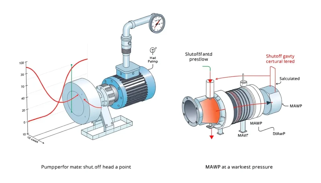
Governing limit: The applicable pressure limit is the lower of Pshutoff and the minimum MAWP (or design pressure) among all pressure-retaining components in the discharge system. The pump shutoff head is a demand; MAWP is an allowable capacity.
| Symbol | Meaning | US unit | SI unit |
|---|---|---|---|
| Hshutoff | Pump shutoff head at zero flow | ft | m |
| SG | Specific gravity of liquid relative to water | dimensionless | dimensionless |
| Psuction,max | Maximum suction pressure at pump inlet | psig | barg |
| Pshutoff | Maximum discharge pressure at zero flow | psig | barg |
| MAWP | Maximum allowable working pressure of weakest component | psig | barg |
Plain-English restatement: The highest pressure the pump can create is its shutoff head converted to pressure plus the highest suction pressure it will ever see; that value must not exceed the lowest MAWP anywhere in the pressure envelope.

Overview — What It Is and Why It Matters
Shutoff head versus maximum working pressure is a common point of confusion in pump-system design. The phrase is sometimes written as “maximum allowable shutoff pressure” on datasheets, but the two quantities answer different questions. Shutoff head is a pump-performance value: the head the pump develops when flow is zero. Maximum working pressure, usually expressed as maximum allowable working pressure (MAWP) or design pressure, is a mechanical limit for a pressure-retaining component. Scope and disambiguation: in this article, maximum working pressure means the MAWP or design pressure of the piping, flanges, instruments, heat exchangers, vessels, and pump casing in the pressure envelope, not a pump curve value.
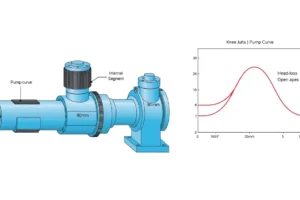
Shutoff head is read from the pump performance curve at the zero-flow end. For a fixed-speed centrifugal pump with a given impeller diameter, it is essentially a single head value for a given fluid and speed. Pressure is different. The pressure produced by that head depends on fluid density, and the pressure at the pump discharge also depends on suction pressure. Therefore, a pump with a high shutoff head in feet may produce a modest pressure with a light hydrocarbon and a much higher pressure with a dense brine.
MAWP is defined for a specific component, temperature, and loading condition. For vessels, ASME Section VIII defines MAWP as the maximum internal pressure permitted for a pressure-retaining component at a coincident metal temperature, based on available thickness and allowable stress. For piping, ASME B31.3 provides allowable-pressure calculations based on wall thickness, outside diameter, allowable stress, quality factor, and thickness coefficient. Flanges have pressure-temperature ratings under ASME B16.5. The governing MAWP for a system is the lowest applicable value among all components and load cases.
The engineering consequence of confusing the two is significant. If the designer uses only the pump design-point discharge pressure, the system may be underprotected when the pump deadheads. If the designer uses only a preliminary 10–20% margin above design head, the final vendor curve may still exceed that estimate. A published case study described a pump initially estimated to produce 25 barg shutoff pressure; the vendor curve later showed 28 barg. The heat exchanger on the discharge had an MAWP of 26 barg, so the exchanger became the weak point. The team ultimately upgraded the exchanger to 30 barg rather than adding a costly relief system. In short, shutoff head sets the maximum pressure demand; MAWP sets the allowable limit; the lower of the two governs.
The Method — Derivation and Variants
The derivation starts with the relationship between head and pressure. Head is energy per unit weight, usually expressed in feet or meters of flowing fluid. Pressure is force per unit area. For a static column of fluid, P = ρ g H, where ρ is density, g is gravitational acceleration, and H is head. In US customary units, it is convenient to use specific gravity instead of density. For water at standard conditions, 1 psi corresponds to approximately 2.31 ft of water. Therefore, for a liquid with specific gravity SG, the pressure in psi produced by a head H in feet is P = H × SG / 2.31.
At pump shutoff, flow is zero, so friction losses in the suction line are also zero. The maximum suction pressure is therefore based on the highest credible static condition: maximum tank level, maximum vessel vapor pressure or relief-valve set pressure, and the elevation difference between the liquid surface and the pump suction centerline. The maximum discharge pressure at shutoff is then the sum of that maximum suction pressure and the pressure equivalent of the pump shutoff head:
US customary: Pshutoff (psig) = Psuction,max (psig) + Hshutoff (ft) × SG / 2.31.
SI: Pshutoff (Pa) = Psuction,max (Pa) + ρ (kg/m³) × 9.81 (m/s²) × Hshutoff (m). Divide by 100,000 to convert Pa to bar, or by 1,000 to convert kPa to bar. The constant 2.31 is not universal; it is the water head-to-pressure conversion for the chosen unit system. For other fluids, specific gravity or density carries the fluid effect.
Variants matter. For a suction vessel with a blanket gas, the maximum suction pressure should use the maximum vessel pressure or the relief-valve set pressure if the vessel is protected. For a tank open to atmosphere, use the highest liquid level. For pumps in series, if all pumps can be at shutoff simultaneously, add the shutoff heads before converting to pressure; the same applies to booster and main pumps. For variable-speed pumps, use the maximum operating speed and the largest impeller expected in service. For fluid properties, use the maximum credible specific gravity, often at the lowest expected temperature. Once Pshutoff is calculated, compare it with the minimum MAWP of every component in the discharge pressure envelope, including the pump casing. The lower value is the governing limit.
Worked Example
Example 1 — US customary units. A centrifugal pump handles water with SG = 1.0. The vendor curve shows a shutoff head Hshutoff = 250 ft with the largest impeller at full speed. The pump takes suction from a tank whose maximum liquid level produces a maximum suction pressure of 15 psig at the pump inlet. The discharge system’s weakest component is a heat exchanger with MAWP = 100 psig. Step 1: convert shutoff head to pressure: 250 / 2.31 = 108.2 psi. Step 2: add maximum suction pressure: Pshutoff = 15 + 108.2 = 123.2 psig. Step 3: compare with MAWP: 123.2 psig > 100 psig. The MAWP is the limiting value; the pump can overpressure the exchanger if it deadheads. Provide engineered overpressure protection or upgrade the exchanger to an MAWP at least equal to 123.2 psig with an appropriate margin. If the exchanger MAWP were 150 psig, the pump shutoff pressure would be the limiting operating pressure, and the system would have about 26.8 psi margin.
Example 2 — SI units. A pump handles a liquid with SG = 1.2. Hshutoff = 80 m. Maximum suction pressure = 3 barg. Using P = Psuction + ρ g H, the density is 1.2 × 1000 = 1200 kg/m³. The head term is 1200 × 9.81 × 80 = 941,760 Pa = 9.4176 bar. Pshutoff = 3 + 9.4176 = 12.42 barg. If the discharge system’s lowest MAWP is 10 barg, the MAWP is the limiting value; the pump can exceed it by about 2.4 bar. If the lowest MAWP is 16 barg, the pump shutoff pressure is the limiting value and the system has about 3.58 bar margin. Note that 1 bar = 100 kPa = 14.5038 psi.
Calculator
For a quick head-to-pressure conversion and total dynamic head checks, use the online calculator at PumpCalcs Total Dynamic Head Calculator. Enter flow, head, and fluid properties, then convert shutoff head to pressure using the formulas above and compare it with the minimum MAWP from the piping and equipment datasheets.
Reference Values & Typical Ranges
Use these values only as screening guidance; always confirm with the governing code, vendor datasheets, and project specifications.
| Item | Typical range or rule of thumb | Notes and source |
|---|---|---|
| Centrifugal pump shutoff head | Often 10–20% above design-point head, but can be higher for low-specific-speed pumps | Read the vendor curve; do not assume a fixed percentage |
| Pump casing MAWP | Often well above system design pressure; API 610 pump casing ratings vary by class and vendor | API 610 and vendor data |
| ASME B16.5 Class 150 flange | About 285 psig at ambient for common carbon steel Group 1.1; lower at higher temperature | ASME B16.5 pressure-temperature ratings |
| ASME B16.5 Class 300 flange | About 740 psig at ambient for common carbon steel Group 1.1 | ASME B16.5 pressure-temperature ratings |
| Design pressure margin | Commonly 10–25% above maximum expected pressure, or per company specification | Company standards; final check uses vendor shutoff head |
| Specific gravity range | Water = 1.0; light hydrocarbons about 0.6–0.9; brines and slurries 1.1–2.0+ | Use maximum credible SG for overpressure checks |
Sources include ASME B31.3 allowable-pressure calculations for process piping, ASME B16.5 flange ratings, API 610 centrifugal pump casing design, and the Boostrand case study in which a preliminary 25 barg shutoff estimate was exceeded by the actual 28 barg vendor value.
Application Guidance
In real systems, the maximum pressure at the pump discharge is not the design-point discharge pressure. It occurs when flow is blocked, a valve is closed, or downstream equipment plugs. At that condition, the pump moves to zero flow and develops shutoff head. The pressure at the discharge is shutoff head converted to pressure plus the suction pressure existing at that moment. Therefore, the maximum suction pressure must be based on the highest credible suction condition: highest tank level, maximum vessel vapor pressure or relief-valve set pressure, and zero friction loss because flow is zero.
Selection implications are straightforward. Specify the pump casing MAWP above the maximum shutoff pressure. Specify all discharge piping, flanges, instruments, heat exchangers, and vessels with MAWP above the maximum shutoff pressure, or provide reliable overpressure protection. The governing limit is the weakest component’s MAWP. Do not accept a pump quotation without the shutoff head at the largest impeller and maximum speed; a design-point head alone is insufficient. For parallel pumps, consider backflow and the case in which one pump deadheads while another runs. For series pumps, add shutoff heads. For fluids that can change density, use the maximum specific gravity credible in operation.
Field-judgment adjustments include verifying the actual impeller diameter after trim, confirming the maximum speed if a variable-frequency drive is used, and checking whether the suction source can ever be at a higher pressure than the normal operating case. If the calculated shutoff pressure exceeds the lowest MAWP, evaluate options in this order: reduce the maximum impeller or speed, upgrade the weakest component, add a relief valve or rupture disk, or add an interlock. The chosen option must be supported by a hazard review and, where applicable, a relief-load calculation.
Common Mistakes, Limits & Safety Notes
- Confusing head with pressure. A head of 250 ft is not 250 psi. Convert using specific gravity and the 2.31 factor in US units, or using ρgH in SI units.
- Using design-point head instead of shutoff head. The design point is not the maximum pressure; the zero-flow end of the pump curve is.
- Ignoring maximum suction pressure. A high tank level, blanket-gas pressure, or relief-valve set pressure can add significantly to shutoff pressure.
- Checking only the pump casing. The weakest component may be a flange, gasket, instrument, heat exchanger, or piping spool.
- Using preliminary pump data. Wait for the vendor curve; a preliminary 20% margin can be inadequate, as the cited case study shows.
- Assuming a relief valve is always acceptable. Relief destination, relief load, and SIL or HAZOP requirements may make protection impractical; upgrading MAWP may be cheaper.
- Forgetting series-pump addition. Multiple pumps in series can produce a shutoff pressure equal to the sum of their shutoff heads after conversion.
- Neglecting fluid density and temperature. Use the maximum credible specific gravity; colder liquid can be denser and produce higher pressure.
Safety note: If the calculated shutoff pressure exceeds the lowest MAWP in the discharge system, do not rely on operator action or a control valve alone. Provide engineered overpressure protection or upgrade the system. Deadhead conditions can occur during valve closure, blockage, or control failure.
FAQ
Is shutoff head the same as maximum working pressure?
No. Shutoff head is a pump performance value: the head developed at zero flow. Maximum working pressure, or MAWP, is a mechanical limit for a piping or equipment component. To compare them, convert shutoff head to pressure using specific gravity and add maximum suction pressure. The lower of the two values governs the design.
What is maximum allowable shutoff pressure?
The term is often used on datasheets to mean the maximum pressure the discharge system can safely tolerate if the pump reaches shutoff. It is not a pump-only property. It should be based on the minimum MAWP of the piping, flanges, instruments, and equipment, or on the pump casing MAWP, whichever is lower.
How do I calculate pump shutoff pressure?
In US units, multiply shutoff head in feet by specific gravity, divide by 2.31, and add maximum suction pressure in psig. In SI, add ρgH to suction pressure in consistent units. Use the largest impeller, maximum speed, and highest credible specific gravity and suction pressure.
Which is higher, shutoff head or MAWP?
They are different quantities, so neither is inherently higher. Shutoff head is a head value; MAWP is a pressure limit. After conversion, either can be higher. If pump shutoff pressure exceeds the lowest MAWP, the MAWP is the limiting value and you need protection or an upgrade. If MAWP is higher, the pump shutoff pressure limits the operating pressure.
Do I need a pressure relief valve if shutoff pressure exceeds MAWP?
Not always. Options include upgrading the weakest component, adding a relief valve, using a rupture disk, interlocking the pump, or limiting speed. The choice depends on relief load, destination, SIL or HAZOP requirements, and cost. A case study found upgrading a heat exchanger MAWP was cheaper than a new relief system.
What is pump casing MAWP?
Pump casing MAWP is the maximum allowable working pressure of the pump casing at the specified temperature, as published by the pump manufacturer. It must be at least equal to the maximum shutoff pressure at the pump discharge. It does not protect downstream piping or equipment, which have their own MAWPs.
How does specific gravity affect shutoff pressure?
Pressure equals head times specific gravity times a constant. For the same shutoff head, a heavier liquid produces higher pressure. Use the maximum credible specific gravity, often at the lowest expected temperature, when checking overpressure. Water has SG 1.0; brines and slurries can exceed 1.2.
What happens if a centrifugal pump runs at shutoff?
At shutoff, flow is zero and the pump develops its maximum head. The liquid can overheat if the pump runs deadheaded for long, and mechanical damage can occur. More immediately for this topic, the discharge pressure reaches its maximum and may exceed the MAWP of downstream components, causing leakage or rupture.

Leave a Reply