
Short Answer
Key Formula / Key Facts Box
| Symbol | Meaning | US Unit | SI Unit | Plain‑English Restatement |
|---|---|---|---|---|
| Q | Volumetric flow rate | GPM | L/s | How many gallons per minute of fluid must circulate. |
| BTU_h | Thermal load | BTU/h | kW | Heat that must be added or removed each hour. |
| ΔT | Temperature rise (or drop) across the coil | °F | K | The allowable temperature change of the fluid. |
| Cp_f | Specific heat of fluid (relative to water) | — | — | Factor that reduces flow when glycol is present. |
| ρ_f | Fluid density | lb/ft³ | kg/m³ | Needed for converting GPM to L/s. |
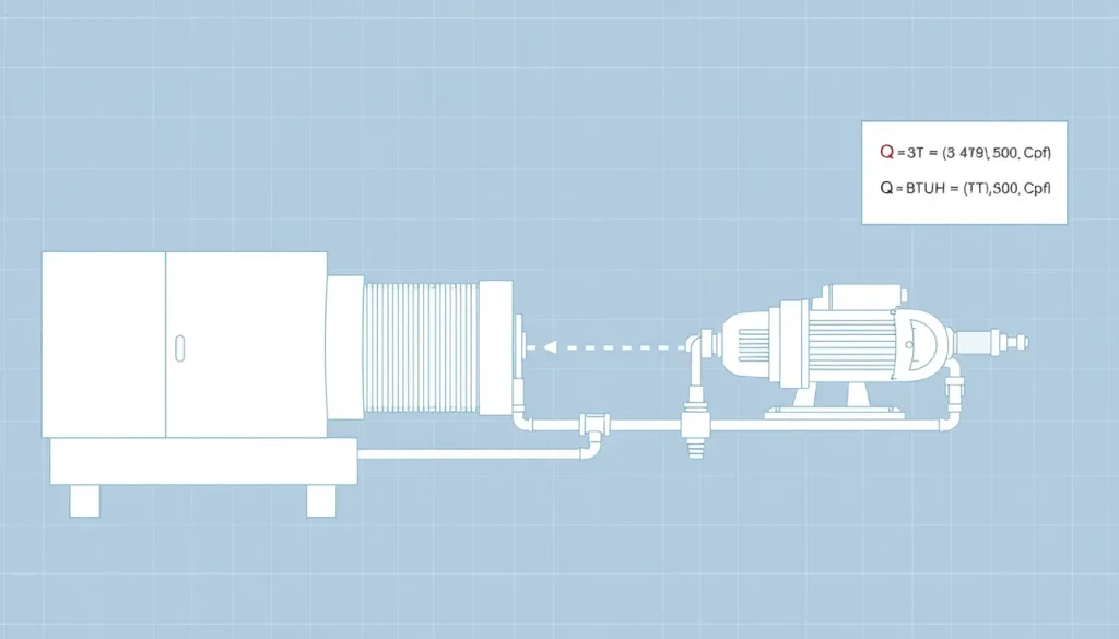
Governing formula (US customary):
[ Q_{text{GPM}} = frac{text{BTU/h}}{Delta T times 500 times C_{p_f}} ]
For SI units the equivalent is:
[ Q_{text{L/s}} = frac{text{kW}times1000}{Delta T times 4.186 times C_{p_f}} ]
Where 500 Btu/(lb·°F) is the product of water density (62.4 lb/ft³) and its specific heat (1 Btu/(lb·°F)). The factor Cp_f accounts for the reduced heat capacity of glycol‑water mixtures (e.g., 0.9 for 30 % glycol).
Overview — What It Is and Why It Matters
In a hydronic HVAC loop the pump’s primary job is to move the heat‑transfer fluid fast enough that the coil (or heat exchanger) sees the temperature swing specified by the design. If the flow is too low, the coil will overheat, cause fouling, reduce comfort, and increase energy use because the system will have to run longer. If the flow is too high, the pump wastes electricity, creates excessive pressure drop, and can lead to cavitation or premature bearing wear. Converting a load expressed in BTU/h (or kW) to a required flow in GPM (or L/s) is the first step in pump selection, pipe sizing, and control‑strategy development.
The Method — Derivation and Variants
Starting with the basic heat‑transfer relation:
[ Q = dot{m},c_p,Delta T ]
where (dot{m}) is mass flow (lb/h), (c_p) is specific heat (Btu/(lb·°F)), and (Delta T) is the temperature change. Mass flow can be expressed as density times volumetric flow:
[ dot{m}=rho times Q_{text{vol}} ]
Substituting and solving for volumetric flow gives:
[ Q_{text{vol}} = frac{text{BTU/h}}{rho,c_p,Delta T} ]
For water at 60 °F, (rho = 62.4,text{lb/ft³}) and (c_p = 1,text{Btu/(lb·°F)}). Multiplying (rho,c_p) yields 62.4, which when converted to GPM (1 ft³ = 7.48 gal) becomes the familiar constant 500. The formula therefore collapses to the simple US version shown above.
When glycol is added, both density and specific heat change. Engineers usually express the change as a single heat‑capacity factor (C_{p_f}) relative to pure water. Typical values (30 % propylene glycol at 70 °F): (C_{p_f}=0.90), (rho_f≈58,text{lb/ft³}). The constant 500 is then multiplied by (C_{p_f}) to reduce the required flow.
SI derivation follows the same steps, using (c_p=4.186,text{kJ/(kg·K)}) for water and (rho≈998,text{kg/m³}). The product (rho c_p) equals 4 186 kJ/(m³·K), which simplifies to the denominator 4.186 when the load is expressed in kW.
Worked Example
Example 1 – US customary units, 30 % glycol
- Design load: 120,000 BTU/h (typical 10‑ton chiller).
- Allowable temperature rise: 12 °F.
- Glycol heat‑capacity factor: 0.90 (from manufacturer data).
- Apply formula: (Q = 120{,}000 / (12 times 500 times 0.90)).
- Calculate: denominator = 12 × 500 × 0.90 = 5,400.
(Q = 120{,}000 / 5{,}400 approx 22.2) GPM. - Convert to L/s for reference: 22.2 GPM × 0.06309 = 1.40 L/s.
Result: a pump capable of delivering at least 22 GPM at the system’s total dynamic head is required.
Example 2 – SI units, 20 % ethylene glycol
- Design load: 35 kW.
- Temperature rise: 6 K.
- Specific‑heat factor for 20 % EG ≈ 0.94.
- Formula: (Q = frac{35{,}000}{6 times 4.186 times 0.94}).
- Denominator = 6 × 4.186 × 0.94 = 23.6.
- (Q = 35{,}000 / 23.6 approx 1,484) L/h → 0.41 L/s.
Result: a small‑capacity circulating pump (≈0.4 L/s) will meet the load.
Calculator
Use an online calculator for quick checks: HVAC Hydronic Flow Calculator.
Reference Values & Typical Ranges
- Water heat capacity factor (Cp_f) = 1.00 (pure water).
- 30 % propylene glycol at 70 °F: Cp_f ≈ 0.90, ρ ≈ 58 lb/ft³.
- Typical ΔT for air‑handler coils: 10–20 °F (5–11 K).
- Common pump flow ranges in commercial buildings: 10–150 GPM (0.6–9.5 L/s).
- Maximum recommended pump speed for copper pipe < 2 in. Ø: 2,500 RPM (to limit erosion).
Application Guidance
When sizing a pump, start with the calculated flow and then add a safety margin of 10–15 % to accommodate fouling, pump‑curve tolerances, and future load growth. Select a pump whose best‑efficiency point (BEP) lies near the system’s design head at the target flow. If the measured pressure drop of the loop (including valves, fittings, and coil) exceeds the pump’s rated head, redesign the piping (larger diameter, smoother fittings) or choose a higher‑head pump.
For glycol mixtures, always obtain the specific‑heat and density from the supplier’s data sheet at the operating temperature; the values vary with concentration and temperature.
Common Mistakes, Limits & Safety Notes
- Unit mix‑up. Plugging kW into the US formula (or BTU/h into the SI version) yields a flow error of ≈3.4×.
- Ignoring glycol heat‑capacity reduction. Assuming Cp_f = 1 for glycol lowers the calculated flow by 5‑15 % and can cause coil overheating.
- Using ΔT that is too small. A 2 °F rise forces a flow that is 3‑4× higher than necessary, oversizing the pump and increasing electricity use.
- Neglecting pressure‑drop calculations. A pump may meet flow but cannot overcome the actual loop head, leading to low‑flow operation.
- Exceeding pump NPSH. High‑speed centrifugal pumps in low‑temperature glycol loops may cavitate if the net positive suction head is inadequate.
- Over‑relying on nominal pump curves. Curves are given at 75 °F water; glycol changes viscosity and shifts the curve. Verify with the manufacturer.
- Skipping a safety margin. Real‑world fouling can increase head loss by 20 % over time; a margin prevents premature pump throttling.
FAQ
Why does the formula use the constant 500 for water?
The constant 500 Btu/(gal·°F) results from multiplying water’s density (62.4 lb/ft³) by its specific heat (1 Btu/(lb·°F)) and converting cubic feet to gallons (1 ft³ = 7.48 gal). It collapses the product ρ·cₚ into a single convenient number for US units.
Can I use the same formula for chilled water loops?
Yes. The equation is based on heat transfer, not temperature direction. Just ensure you use the correct ΔT (typically 6‑10 °F for chilled water) and adjust Cp_f if glycol is added for freeze protection.
How accurate is a 10 % safety margin?
Industry practice shows that fouling, valve wear, and temperature‑set‑point drift usually increase pressure loss by 10‑20 % over the design life. A 10 % flow margin is a practical compromise that avoids oversized pumps while providing head reserve.
What if my pump curve is given at 75 °F water but I’m using glycol at 40 °F?
Glycol raises fluid viscosity, shifting the pump curve to the right (lower flow for a given head). Request a corrected curve from the manufacturer or apply a viscosity correction factor (≈1.2‑1.5× for 30 % glycol at 40 °F).
Do I need to recalculate flow if the building’s load changes seasonally?
Seasonal load variations affect the required flow only if ΔT is held constant. In practice, designers size the pump for the peak load and rely on variable‑speed drives to modulate flow for lower loads, avoiding multiple recalculations.
Is there a quick way to convert GPM to L/s without a calculator?
Multiply GPM by 0.06309 (1 GPM ≈ 0.06309 L/s). Conversely, divide L/s by 0.06309 to obtain GPM.
How do I select the right pipe diameter after I know the flow?
Use the Darcy‑Weisbach or Hazen‑Williams equation to keep velocity between 3‑7 ft/s (0.9‑2.1 m/s) for water; glycol’s higher viscosity calls for the lower end of that range to limit pressure loss.
Can I ignore the density change when using glycol?
Density affects the conversion from GPM to L/s and the NPSH calculation, but its impact on the flow‑sizing equation is captured in the Cp_f factor. For most design work, using the Cp_f factor is sufficient; however, verify NPSH separately with the actual density.


Leave a Reply