
Short Answer
Key Formula / Key Facts Box
Specific Gravity (SG): SG = ρ_f / ρ_w
Dynamic Viscosity (μ): μ = ν·ρ_f
| Symbol | Meaning | US Unit | SI Unit | Plain‑English Restatement |
|---|---|---|---|---|
| ρ_f | Fluid density | lb/ft³ | kg/m³ | Mass per unit volume of the fluid |
| ρ_w | Water density (4 °C) | 62.4 lb/ft³ | 1000 kg/m³ | Reference density of pure water |
| ν | Kinematic viscosity | cSt (mm²/s) | mm²/s | Viscosity per unit density |
| μ | Dynamic viscosity | cP (mPa·s) | Pa·s | Fluid’s resistance to shear |
Overview — What It Is and Why It Matters
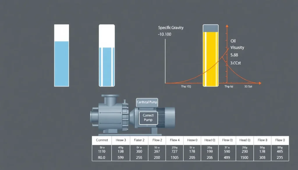
Specific gravity (SG) is a dimensionless ratio that compares a fluid’s density to that of water at 4 °C. Because most pump performance curves are generated with water as the reference fluid, SG directly scales head, power, and flow calculations. Viscosity, expressed as either dynamic (μ) or kinematic (ν), quantifies a fluid’s internal friction and determines how much additional head a pump must generate to overcome flow resistance. Errors in SG or viscosity lead to oversized motors, cavitation, excessive wear, and energy penalties.
The Method — Derivation and Variants
Starting from the definition of density (ρ = mass/volume), SG follows immediately:
SG = ρ_f / ρ_w.
In US customary practice the numerator is in lb/ft³ and the denominator is the standard water density of 62.4 lb/ft³. In SI, both densities are expressed in kg/m³, making the ratio unit‑free.
Viscosity can be measured as:
- Dynamic viscosity (μ) – the shear stress per unit velocity gradient (Pa·s or cP).
- Kinematic viscosity (ν) – dynamic viscosity divided by density (m²/s or cSt).
The conversion between the two is μ = ν·ρ_f. When using US units, μ (cP) = ν (cSt) × SG, because 1 cSt = 1 mm²/s and 1 cP = 0.001 Pa·s.
For pump‑selection calculations the most common variant is the “viscosity correction factor” K_v, defined by the Hydraulic Institute (HI) as:
K_v = 1 + 0.02·(ν – 1) for ν up to 100 cSt (approximation for centrifugal pumps). The factor multiplies the required head.
Worked Example
Example 1 – US Customary (oil in a chemical plant)
Fluid: Light mineral oil, 20 °C.
Given: SG = 0.88, kinematic viscosity ν = 3.5 cSt.
Pump: 150 hp centrifugal pump rated at 150 ft head with water.
Find: Adjusted head required for the oil.
- Calculate K_v: K_v = 1 + 0.02·(3.5 – 1) = 1 + 0.02·2.5 = 1.05.
- Adjust head for SG (water‑based head scales with SG): H_adj = 150 ft × SG = 150 ft × 0.88 = 132 ft.
- Apply viscosity correction: H_final = H_adj × K_v = 132 ft × 1.05 ≈ 138.6 ft.
Result: The pump must develop roughly 139 ft of head for the oil, a 6 % increase over the water‑based rating.
Example 2 – SI (high‑viscosity syrup in food processing)
Fluid: Fruit syrup, 25 °C.
Given: SG = 1.32, ν = 45 cSt.
Pump: 0.2 kW centrifugal pump rated at 25 kPa head with water.
Find: Adjusted head in kPa.
- Convert water head to kPa: 25 kPa (given).
- Viscosity correction factor (HI approximation for ν ≤ 100 cSt): K_v = 1 + 0.02·(45 – 1) = 1 + 0.02·44 = 1.88.
- Scale head by SG: H_adj = 25 kPa × 1.32 = 33 kPa.
- Apply K_v: H_final = 33 kPa × 1.88 ≈ 62 kPa.
Result: The pump must deliver about 62 kPa (≈ 6.3 m of water) when handling the syrup.
Calculator
For quick conversions and correction‑factor calculations, visit the online tool: Pump Total Dynamic Head Calculator.
Reference Values & Typical Ranges
| Fluid | SG (25 °C) | Dynamic Viscosity μ (cP) | Kinematic Viscosity ν (cSt) |
|---|---|---|---|
| Water | 1.00 | 1.0 | 1.0 |
| Light mineral oil | 0.88 | 0.25 | 3.5 |
| Diesel fuel | 0.85 | 2.0 | 2.4 |
| Motor oil (ISO VG 46) | 0.86 | 46 | 53 |
| Glycerin (30 % solution) | 1.12 | 6.0 | 5.4 |
| Honey (room temp) | 1.42 | 10,000 | 7,000 |
| Air (20 °C, 1 atm) | 0.0012 | 0.018 | 15.0 |
Sources: ASTM D4052, ISO 3104, Hydraulic Institute Standards.
Application Guidance
- Pump Selection: Adjust the manufacturer’s head‑curve by SG and apply K_v for fluids with ν > 1 cSt. For positive‑displacement pumps, use viscosity‑ratio charts rather than K_v.
- System Sizing: Pipe friction losses increase roughly with the square of viscosity; use the Moody diagram with an effective Reynolds number Re = (4·Q)/(π·D·ν).
- Temperature Effects: Both SG and ν are temperature‑dependent. Obtain viscosity at operating temperature or apply the Arrhenius‑type temperature correction: ν_T = ν_Tref·e^{−β(T−Tref)}.
- Field Adjustments: If on‑site measurements differ > 5 % from catalog values, re‑evaluate pump duty point and consider a larger motor or a different pump type.
Common Mistakes, Limits & Safety Notes
- Mixing US and SI units in the same calculation (e.g., using lb/ft³ with kg/m³) leads to SG errors of up to 30 %.
- Assuming water‑based efficiency curves are valid for fluids with ν > 100 cSt; centrifugal pumps lose efficiency dramatically beyond this range.
- Neglecting temperature‑induced viscosity changes; a 10 °C rise can halve the viscosity of many oils.
- Applying the HI viscosity correction factor to positive‑displacement pumps – it is only calibrated for centrifugal machines.
- Using SG values measured at 20 °C for fluids that are significantly lighter/heavier at 4 °C; water density varies with temperature, affecting the reference.
- Overlooking cavitation risk when SG < 0.8; lower density reduces NPSH available, requiring higher NPSH design.
- Ignoring safety data sheets (SDS) for highly viscous, hazardous fluids; high viscosity can cause pump seizure and lead to mechanical failure.
FAQ
How does specific gravity affect pump head calculations?
Because pump head is proportional to the weight of the fluid, you multiply the water‑based head by the fluid’s SG. A fluid lighter than water (SG 1) increases it.
When should I use dynamic viscosity instead of kinematic viscosity?
Dynamic viscosity (μ) is needed when shear stress calculations are required, such as in sealing or bearing analysis. Kinematic viscosity (ν) is preferred for flow‑field calculations because it incorporates density, simplifying Reynolds‑number evaluation.
Can I apply the HI viscosity correction factor to a gear pump?
No. The HI factor is calibrated for centrifugal pumps. Positive‑displacement pumps like gear, screw, or vane types have different slip characteristics and usually require manufacturer‑provided correction curves.
What temperature range is safe for using catalog viscosity values?
Catalog values are typically given at 40 °C or 20 °C. If operating more than ±10 °C away, apply temperature‑correction formulas or measure viscosity on‑site to avoid large errors.
Why does low specific gravity increase cavitation risk?
Lower SG means the fluid is lighter, reducing the available NPSH. With less head margin, the pump is more prone to local pressure falling below vapor pressure, causing cavitation.
Is it acceptable to ignore viscosity for fluids with ν < 1 cSt?
For most centrifugal pumps, ν < 1 cSt (essentially water‑like) has a negligible effect, and the HI correction factor defaults to 1.0. However, very high‑speed pumps may still experience minor losses.
How do I convert cSt to cP for a fluid with known SG?
Use μ (cP) = ν (cSt) × SG. For example, ν = 5 cSt and SG = 0.9 give μ = 4.5 cP.
What is the impact of high viscosity on pump power consumption?
Viscous fluids increase internal friction, raising the required head and therefore motor power. Roughly, each 10 cSt increase can add 2‑4 % to the power demand, depending on pump design.

Leave a Reply