
Short Answer
Key Formula / Key Facts Box
Governing Formula (Total Dynamic Head, TDH)
TDH = H_s + H_f + H_p
| Symbol | Meaning | US Unit | SI Unit | Plain‑English Restatement |
|---|---|---|---|---|
| H_s | Static head (vertical lift) | ft | m | the vertical distance the water must be raised |
| H_f | Friction loss in pipe | ft | m | energy lost due to pipe resistance |
| H_p | Pressure head required at point of use | ft | m | extra head to overcome fixture pressure |
| Q | Flow rate | gpm | L/s | volume of water delivered per minute |
| η | Pump efficiency | % | % | ratio of hydraulic power to shaft power |
TDH is the sum of all heads the pump must overcome to deliver the required flow.
Overview — What It Is and Why It Matters
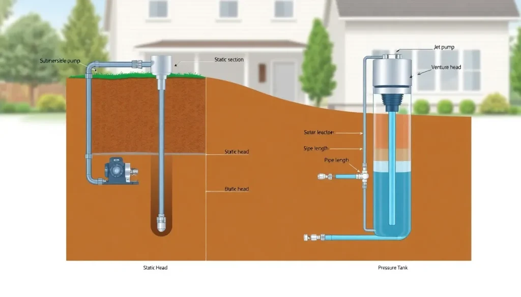
Well pump sizing is the process of selecting a pump whose hydraulic performance matches the demand of a home’s water system. The two most common residential well‑pump technologies are submersible pumps, which operate downhole, and jet pumps, which sit above the water level and use a venturi‑type ejector. An undersized pump leads to low pressure, frequent cycling, and premature motor wear, while an oversized unit wastes electricity and may cause water hammer. Accurate sizing therefore protects the homeowner’s comfort, prolongs equipment life, and ensures compliance with local plumbing codes.
The Method — Derivation and Variants
The starting point for any pump‑selection problem is the energy equation for incompressible flow, expressed as a head balance:
z₁ + p₁/γ + v₁²/2g = z₂ + p₂/γ + v₂²/2g + h_f + h_p
When velocities at the inlet and outlet are small compared with the elevation terms, the kinetic contributions cancel, yielding the familiar TDH expression shown in the Key Facts Box. In US customary practice the equation is written in feet of water; in SI it is written in meters. The conversion factor is 1 ft ≈ 0.3048 m.
Two variants are commonly used:
- Static‑only TDH – for shallow wells where pipe friction is negligible (< 10 ft or 3 m). The equation reduces to H_s + H_p.
- Full‑system TDH – for deeper wells, long‑run pipe, or high‑flow fixtures. Here H_f is calculated from the Darcy–Weisbach or Hazen‑Williams formula, depending on the design code (ANSI/ASME B31.3 for commercial, ANSI/ASME A17.1 for residential).
Once TDH is known, the required pump horsepower (HP) follows from:
HP = (Q × TDH) / (3960 × η)
where 3960 is the conversion constant for US units (gpm·ft to HP). In SI the equivalent constant is 0.746 kW per kW·m, giving:
kW = (Q × TDH) / (η × 1000)
These equations apply to both submersible and jet pumps; the difference lies in the available head‑flow curves supplied by manufacturers.
Worked Example
Scenario A – US Units (Submersible)
A single‑family home draws 12 gpm at a peak demand of 55 psi (≈ 125 ft H₂O). The well depth is 250 ft, the static water level sits 40 ft below ground, and the discharge pipe is 75 ft of 1‑in. copper (≈ 0.02 ft/100 ft per gpm). Assume a pump efficiency of 70 %.
- Static head: H_s = 250 ft (depth) – 40 ft (water level) = 210 ft.
- Pressure head: H_p = 125 ft.
- Friction loss (Hazen‑Williams):
H_f = 0.02 ft/100 ft × (12 gpm)² × (75 ft/100 ft) ≈ 2.2 ft.
- TDH = 210 + 125 + 2.2 ≈ 337 ft.
- Required hydraulic power: Q × TDH = 12 gpm × 337 ft = 4044 gpm·ft.
- Brake horsepower: HP = 4044 / (3960 × 0.70) ≈ 1.46 HP.
Choosing the next standard size, a 1.5 HP submersible pump with a 340 ft head curve at 12 gpm satisfies the requirement.
Scenario B – SI Units (Jet Pump)
A rural house uses a shallow well (well depth 15 m, static water level 3 m below ground). Desired flow is 45 L/min at 300 kPa (≈ 30 m H₂O). Pipe run: 30 m of 20 mm PVC (≈ 0.08 m/100 m per L/min). Pump efficiency 60 %.
- Static head: H_s = 15 m – 3 m = 12 m.
- Pressure head: H_p = 30 m.
- Friction loss: H_f = 0.08 m/100 m × (45 L/min)² × (30 m/100 m) ≈ 0.49 m.
- TDH = 12 + 30 + 0.49 ≈ 42.5 m.
- Hydraulic power: Q × TDH = 0.045 m³/s × 42.5 m = 1.91 kW.
- Brake power: kW = 1.91 / 0.60 ≈ 3.18 kW (≈ 4.3 HP).
A 4‑kW (5‑HP) jet pump with a 45 L/min rating at 42 m head meets the design point, leaving a small safety margin for future demand spikes.
Calculator
For quick on‑line sizing, use the Total Dynamic Head calculator at http://pumpcalcs.com/calculators/total-dynamic-head/. It accepts both US and SI inputs and outputs required horsepower.
Reference Values & Typical Ranges
- Typical residential static heads: 30–250 ft (9–75 m).
- Jet‑pump practical head limit: ≤ 100 ft (30 m) – beyond this a submersible is more efficient.
- Submersible pump efficiency: 60–85 % (peak near best‑efficiency point).
- Jet‑pump efficiency: 40–55 % (lower due to ejector losses).
- Recommended pipe diameter for 12 gpm: ¾‑in. copper or ½‑in. PEX to keep H_f < 5 % of TDH.
Sources: ANSI/ANSI/ISA‑75.01.01, ISO 9906, and “Pump Handbook” (McGraw‑Hill, 2018).
Application Guidance
When deciding between submersible and jet pumps, consider:
- Well depth – Shallow wells (< 25 ft / 7.5 m) can use jet pumps; deeper wells require submersibles.
- Space constraints – Jet pumps sit above ground, simplifying maintenance; submersibles need a well casing and retrieval rope.
- Water quality – Submersibles are sealed and handle sand‑laden water better; jet pumps are more susceptible to clogging.
- Energy cost – Submersibles usually have higher efficiency and lower operating cost for high heads.
- Future expansion – Size the pump for the highest anticipated demand (e.g., simultaneous shower, washing machine, irrigation).
After selecting a pump, verify that the motor’s service factor matches the expected duty cycle (continuous vs intermittent) and that the electrical supply meets voltage and phase requirements.
Common Mistakes, Limits & Safety Notes
- Mixing units – Using ft for head but gallons per minute for flow without converting to the 3960 constant leads to under‑ or over‑estimation of horsepower.
- Ignoring friction loss – Long pipe runs can add > 10 % to TDH; omitting H_f results in undersized pumps.
- Choosing a jet pump for > 100 ft head – The ejector cannot generate the required suction, causing cavitation and motor burnout.
- Neglecting pump curve intersection – Selecting a pump based solely on rated head ignores the actual flow‑head curve; the operating point may fall off the efficient region.
- Over‑pressurizing the system – Installing a pump that delivers pressure far above code‑required (typically 50–60 psi) can strain fixtures and cause leaks.
- Improper grounding and enclosure – Submersible motors must be grounded and placed in a dry, ventilated wellhead box to prevent electrical hazards.
- Forgetting priming requirements – Jet pumps need a filled suction line; air pockets cause loss of prime and pump failure.
Adhering to these guidelines keeps the system safe, efficient, and compliant with ANSI/ASME standards.
FAQ
Can I replace a submersible pump with a jet pump if my well gets deeper?
No. Jet pumps rely on suction and are limited to roughly 100 ft (30 m) of total head. Exceeding that causes cavitation and loss of prime. For deeper wells, a submersible pump is the only reliable solution.
How often should I inspect the pressure tank when using a jet pump?
Inspect the pressure tank at least once a year for proper pre‑charge pressure and signs of corrosion. A faulty tank can cause short‑cycling of the jet pump, reducing efficiency and increasing wear.
What size motor do I need for a 1.5 HP submersible pump?
Select a motor rated at the same horsepower (1.5 HP) with a service factor of 1.2 or higher, and ensure the voltage, phase, and enclosure rating match the well‑head environment.
Why is friction loss more critical for jet pumps than for submersibles?
Jet pumps operate at the surface, so the entire suction line contributes to head loss. Submersibles are already at the required depth, making pipe friction a smaller portion of the total head.
Is it safe to run a submersible pump continuously?
Yes, provided the motor is rated for continuous duty, the well water level remains above the pump’s minimum immersion depth, and the electrical installation follows NEC grounding rules.
How do I calculate pipe friction loss without software?
Use the Hazen‑Williams formula for water: H_f = 4.52 × Q^1.85 × L / (C^1.85 × D^4.87), where Q is flow in gpm, L is length in ft, D is pipe internal diameter in inches, and C is the pipe‑roughness coefficient (≈ 130 for copper).
Leave a Reply