
Short Answer
Key Formula / Key Facts Box
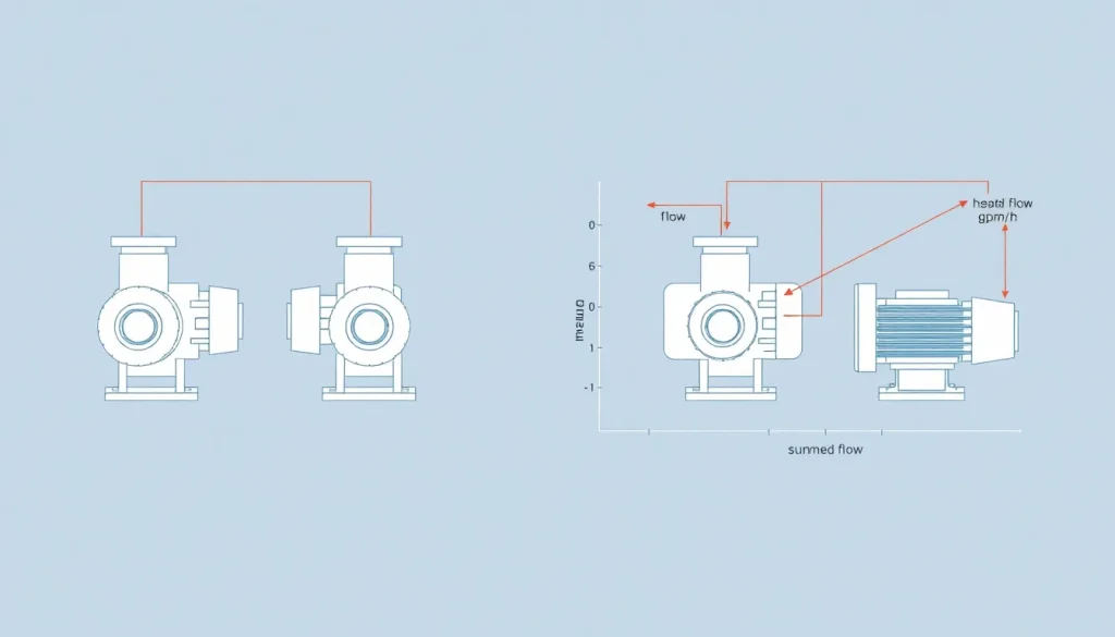
Series Connection
[ H_{total}=sum_{i=1}^{n} H_i qquad Q_{total}=Q_i ]
Parallel Connection
[ Q_{total}=sum_{i=1}^{n} Q_i qquad H_{total}=H_i ]
| Symbol | Meaning | US Unit | SI Unit | Plain‑English |
|---|---|---|---|---|
| H | Total dynamic head | ft | m | Energy per unit weight delivered by the pump |
| Q | Volumetric flow rate | gpm | m³/h | Quantity of fluid moved per time |
| n | Number of identical pumps | — | — | How many pumps are linked together |
| H_i | Head produced by pump i | ft | m | Individual pump contribution to head |
| Q_i | Flow produced by pump i | gpm | m³/h | Individual pump contribution to flow |
Overview — What It Is and Why It Matters
When a system requires more head than a single pump can provide, engineers often connect pumps in series. Conversely, when higher flow is needed without increasing head, pumps are placed in parallel. The way performance curves combine directly influences motor sizing, pipe sizing, and overall plant efficiency. Misapplying series‑parallel logic can cause cavitation, oversized motors, or costly redesigns.
The Method — Derivation and Variants
Start with the generic pump characteristic expressed as H = f(Q). For identical pumps:
- Series: The discharge of pump 1 becomes the suction of pump 2, so the flow remains constant while heads add. Mathematically,
H_total = H_1 + H_2 + … + H_nandQ_total = Q_1 = Q_2 = … = Q_n. - Parallel: All pumps share the same suction and discharge pressure, so each sees the same head. Flows sum:
Q_total = Q_1 + Q_2 + … + Q_nwhileH_total = H_1 = H_2 = … = H_n.
In US‑customary form the equations use feet and gallons‑per‑minute; in SI they use metres and cubic metres per hour. The constants are unity because head and flow are additive quantities; no conversion factor is needed other than unit consistency.
Worked Example
Example 1 – US Units, Series Connection
Three identical 10 in‑shaft centrifugal pumps each deliver a head‑curve H = 150 – 0.02 Q (ft, gpm). Determine the combined head at a system flow of 600 gpm.
- Because pumps are in series, the flow through each pump equals the system flow:
Q_i = 600 gpm. - Insert into the single‑pump equation:
H_i = 150 – 0.02×600 = 138 ft. - Add the heads:
H_total = 3 × 138 = 414 ft.
Result: The three‑pump train can overcome 414 ft of head at 600 gpm.
Example 2 – SI Units, Parallel Connection
Two identical vertical turbine pumps each have a characteristic H = 45 – 0.005 Q (m, m³/h). Find the total flow when the system requires 30 m of head.
- Set the head equal to the required system head:
45 – 0.005 Q_i = 30 → Q_i = (45‑30)/0.005 = 3000 m³/h. - Because pumps are in parallel, total flow is the sum:
Q_total = 2 × 3000 = 6000 m³/h.
Result: The parallel pair delivers 6 000 m³/h while maintaining the 30 m head.
Calculator
Use an online pump series‑parallel calculator for quick verification: Pump Calculations – Total Dynamic Head
Reference Values & Typical Ranges
- Series configuration is common for high‑rise water supply, mine dewatering, and boiler feed‑water where total heads exceed 300 ft (≈90 m).
- Parallel configuration is typical in municipal water mains, cooling‑tower recirculation, and process streams where flow rates of 10 000–100 000 gpm (≈38–380 m³/h) are required.
- Efficiency penalties: series adds frictional losses of roughly 0.5 % per additional pump; parallel reduces net system NPSH by 0.1–0.3 ft per added unit.
- Rule of thumb: Do not exceed a head increase of 3× the single‑pump rating in series; do not exceed a flow increase of 2–3× in parallel without re‑evaluating pipe sizing.
Application Guidance
When deciding between series and parallel, follow these steps:
- Plot the system curve (head vs. flow) from pipe friction, static lift, and minor losses.
- Overlay the single‑pump characteristic. Identify whether the intersection point lies below the desired head (need series) or left of the desired flow (need parallel).
- Consider motor ratings: series adds head but keeps flow constant, so motor power grows roughly linearly with head. Parallel keeps head constant, power grows with flow.
- Re‑calculate NPSH available after each configuration change; series may reduce suction pressure, parallel may increase suction demand.
- Validate the combined curve using the formulas above before finalizing equipment specifications.
Common Mistakes, Limits & Safety Notes
- Mixing units: Adding a head in metres to one in feet yields a nonsensical result. Convert all quantities to a single system first.
- Assuming identical pumps: Real‑world installations often involve pumps of different size or impeller speed; the simple additive rules only hold for identical, similarly operating units.
- Neglecting pipe‑line losses between pumps: Series connections add extra piping, increasing friction loss; failure to account for this can over‑predict achievable head.
- Over‑loading motors: In series, motor torque must handle the increased head; in parallel, each motor must handle the higher flow‑related power. Verify motor curves.
- Ignoring NPSH: Series suction can drop below NPSH required, leading to cavitation. Parallel configurations can raise inlet velocity, also affecting NPSH.
- Exceeding design limits: Manufacturers typically limit series combinations to 2–3 units; beyond that, efficiency drops sharply and warranty coverage may be void.
FAQ
Can I mix series and parallel connections in the same system?
Yes, hybrid configurations are used when both high head and high flow are needed, but each stage must be analyzed separately and the combined curve derived step‑by‑step.
How do I know if my pumps are truly identical for the additive formulas?
Check that impeller diameter, rotational speed, and hydraulic design are the same, and that the manufacturers list them as “matched units” for series/parallel operation.
Does the pipe diameter need to change when adding pumps in parallel?
Often it does; parallel flow doubles (or triples) the velocity, so pipe size may need to be increased to keep friction losses within acceptable limits.
What happens to the system curve when pumps are placed in series?
The system curve stays unchanged; only the pump curve shifts upward because head adds while flow stays constant.
Is it safe to run three pumps in series for a fire‑suppression system?
Fire‑pump codes usually limit series to two units and require a detailed hydraulic analysis to ensure NPSH and motor ratings are adequate.
Why does efficiency drop when adding more pumps in parallel?
Inter‑pump interference, increased suction velocity, and higher Reynolds numbers raise hydraulic losses, reducing overall efficiency.
Can I use the same motor for a pump that is moved from series to parallel operation?
Only if the motor’s torque and power curves cover both the higher head (series) and higher flow (parallel) demands; otherwise a motor upgrade is required.
How do I account for additional pipe length between series pumps?
Add the calculated friction loss of the inter‑pump piping to the system curve before re‑evaluating the combined head.

Leave a Reply