
Short Answer
Key Formula / Key Facts Box
| Symbol | Meaning | US Unit | SI Unit | Notes |
|---|---|---|---|---|
| P_atm | Atmospheric pressure at the suction point | psia | kPa | Measured at site elevation |
| P_vap | Vapor pressure of the liquid at suction temperature | psia | kPa | From steam‑tables or property data |
| z_s | Static head (positive for flooded, negative for lift) | ft | m | Elevation difference between liquid surface and pump centreline |
| h_f | Friction loss in suction piping | ft | m | Calculated with Darcy‑Weisbach or Hazen‑Williams |
| h_v | Velocity head at the pump inlet | ft | m | v²/(2g) |
| NPSHA | Net Positive Suction Head Available | ft | m | Must exceed NPSHR for cavitation‑free operation |
Formula: NPSHA = (P_atm – P_vap)/(ρ g) + z_s – h_f – h_v
Overview — What It Is and Why It Matters
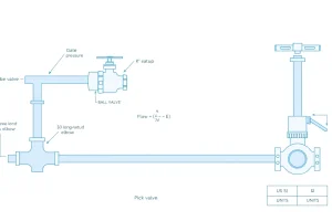
Suction lift occurs when a pump draws fluid from a source that lies below the pump inlet; the pump must overcome a negative static head together with all friction and velocity losses. Flooded suction, by contrast, supplies the pump from a reservoir that is at or above the inlet, giving a positive or zero static head. The distinction directly governs the Net Positive Suction Head Available (NPSHA). Insufficient NPSHA leads to cavitation, reduced efficiency, vibration, and premature seal or impeller damage. Designing the suction side correctly therefore protects equipment, meets the required head, and optimises energy consumption.
The Method — Derivation and Variants
Applying the Bernoulli equation between the liquid surface (point 1) and the pump inlet (point 2) yields:
(P_atm/γ) + z₁ = (P₂/γ) + z₂ + h_f + h_v
Re‑arranging for the pressure head at the inlet gives the NPSHA expression shown in the key box. In US‑customary units γ is the specific weight of the fluid (lb/ft³); in SI units the term ρ g replaces γ and all heads are expressed in metres.
Two practical variants are commonly used:
- Standard‑Atmosphere Variant: P_atm is fixed at 14.696 psia (101.325 kPa) for sea‑level conditions, with altitude corrections applied via a pressure‑reduction factor.
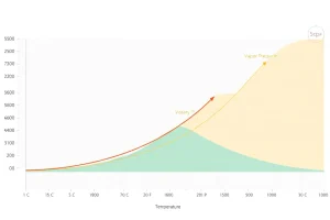
- Temperature‑Corrected Variant: P_vap is evaluated at the actual suction temperature, which can vary dramatically for volatile liquids or hot process streams.
Both variants share the same gravitational constant (g = 32.174 ft/s² or 9.80665 m/s²) and the same loss‑term calculations. The choice depends on whether a generic sea‑level design or a high‑altitude, temperature‑sensitive application is being performed.
Worked Example
Example 1 – US Customary (Suction Lift)
A 2‑in. centrifugal pump is installed 12 ft below a groundwater table. The suction line is 30 ft long of 2‑in. Schedule 40 steel (C ≈ 0.03 ft). Flow = 150 gpm of water at 68 °F (P_vap ≈ 0.018 psia). Determine NPSHA.
- Atmospheric pressure at sea level: P_atm = 14.696 psia.
- Static lift: z_s = –12 ft (negative because the source is below the pump).
- Velocity at the inlet: v = Q/A ≈ 23.6 ft/s. Velocity head h_v = v²/(2g) ≈ 8.6 ft.
- Friction loss (Darcy‑Weisbach): h_f = f·(L/D)·v²/(2g). With f ≈ 0.02, L/D ≈ 179.6, the loss is ≈ 31.4 ft.
- Pressure‑head term: (P_atm – P_vap)/γ ≈ (14.696 – 0.018)/0.052 ≈ 282 ft.
- Finally, NPSHA = 282 ft + (–12 ft) – 31.4 ft – 8.6 ft ≈ 230 ft.
Result: NPSHA ≈ 230 ft, far above a typical NPSHR (< 30 ft), so cavitation is not a concern.
Example 2 – SI (Flooded Suction)
A 50 kW centrifugal pump draws water from a tank whose surface sits 3 m above the pump centreline. Suction pipe length = 8 m, DN 50 (Ø = 0.05 m), flow = 0.03 m³/s, water temperature = 20 °C (P_vap = 2.34 kPa). Determine NPSHA.
- Atmospheric pressure at sea level: P_atm = 101.325 kPa.
- Static head: z_s = +3 m.
- Velocity: v = Q/A ≈ 3.06 m/s. Velocity head h_v ≈ 0.48 m.
- Friction loss (Darcy‑Weisbach, f ≈ 0.018): h_f ≈ 0.65 m.
- Pressure‑head term: (P_atm – P_vap)/(ρ g) ≈ (101.325 – 2.34)/(998·9.80665) ≈ 9.95 m.
- NPSHA = 9.95 m + 3 m – 0.65 m – 0.48 m ≈ 11.8 m.
Result: NPSHA ≈ 11.8 m, comfortably exceeding a typical NPSHR of 2–3 m for a 50 kW pump.
Calculator
For rapid verification, use an online suction‑side calculator: PumpCalcs – Suction NPSH Calculator.
Reference Values & Typical Ranges
- Maximum practical suction lift for water at sea level: 7.5 ft (2.3 m). Beyond this limit cavitation is almost certain.
- Acceptable NPSHA margin: NPSHA ≥ NPSHR + 3 ft (≈ 1 m) for safe operation.
- Friction‑loss coefficient (C) for steel pipe (Hazen‑Williams) at 60 °F: 130–150.
- Velocity head for typical suction velocities (3–6 ft/s or 0.9–1.8 m/s): 0.1–0.5 ft (0.03–0.15 m).
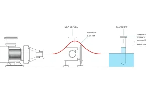
- Altitude correction: Reduce atmospheric pressure by ≈ 0.5 psia per 1,000 ft (≈ 5 kPa per 300 m).
Application Guidance
When selecting a pump, first decide whether the source can provide a flooded condition. If the suction point lies below the liquid level, calculate the theoretical lift and compare it with the practical limit of 7.5 ft (2.3 m). If lift is required, consider the following actions:
- Increase suction pipe diameter to reduce velocity and friction losses.
- Choose low‑roughness materials (e.g., stainless‑steel, PVC) to lower the Darcy friction factor.
- Install a submersible or booster pump upstream to convert lift into flooded suction.
- Verify that the pump’s NPSHR curve is evaluated at the intended operating flow.
For flooded suction designs, focus on minimizing h_f and h_v by keeping runs short, using straight pipe runs, and limiting elbows or fittings.
Common Mistakes, Limits & Safety Notes
- Mixing units. Inserting kPa values into a US‑customary formula (or vice‑versa) yields nonsensical NPSHA results.
- Neglecting temperature‑dependent vapor pressure. Hot or volatile liquids have much higher P_vap; ignoring this can erase the NPSHA margin.
- Assuming zero velocity head. Even modest flow rates generate measurable h_v; omission underestimates total losses.
- Relying on a single NPSHR point. NPSHR varies with flow; always use the full curve rather than a single quoted value.
- Exceeding the practical suction lift limit. Attempting to lift water > 7.5 ft at sea level almost always results in cavitation.
- Ignoring altitude effects. At 3,000 ft the atmospheric head drops ≈ 1.5 ft, shrinking the NPSHA budget.
- Choosing inappropriate pipe material. Rough interiors increase the friction factor, raising h_f and reducing NPSHA.
- Safety hazard. Cavitation can cause rapid pressure spikes that damage impellers and produce hazardous debris; proper NPSHA design mitigates this risk.
FAQ
Why can a centrifugal pump not lift water more than 7‑8 ft?
Because the atmospheric head at sea level is only about 14.7 psi (≈ 34 ft). After accounting for vapor pressure, velocity head, and friction losses, the remaining NPSHA drops below the pump’s required NPSHR once the lift exceeds roughly 7 ft. Below this limit the pump can maintain positive suction pressure without cavitation.
Can I use a larger suction pipe to eliminate cavitation in a lift application?
A larger pipe reduces velocity and friction losses, which raises NPSHA, but it cannot overcome the fundamental atmospheric limit. It helps improve margin up to the practical lift ceiling of about 7 ft. Beyond that, a submersible or booster pump is required because the available atmospheric head is insufficient regardless of pipe size.
How does altitude affect suction lift calculations?
Atmospheric pressure decreases with elevation, reducing the pressure‑head term (P_atm – P_vap)/(ρ g) in the NPSHA equation. For example, at 5,000 ft the atmospheric head is roughly 12.2 psi (≈ 28 ft), shrinking the NPSHA budget by about 6 ft compared with sea level. Designers must apply an altitude correction factor to maintain adequate NPSHA margin.
What is the difference between NPSHA and NPSHR, and why are both needed?
NPSHA (Net Positive Suction Head Available) is the actual head at the pump inlet after accounting for static head, friction, velocity, and vapor pressure. NPSHR (Net Positive Suction Head Required) is the minimum head the pump needs to avoid cavitation at a specific flow rate, provided by the manufacturer. Both are compared to ensure NPSHA ≥ NPSHR for safe operation.
When should I consider a submersible pump instead of a standard suction lift arrangement?
If the required lift approaches or exceeds the practical limit of 7 ft (2.3 m) or if the installation site has high temperature liquids with elevated vapor pressure, a submersible pump placed below the liquid surface eliminates lift entirely. This converts the problem to flooded suction, maximising NPSHA and reducing the risk of cavitation and excessive pipe friction.
How do I account for viscous liquids such as oil in suction‑side design?
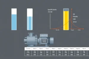
Viscous fluids increase the Darcy friction factor and often have higher vapor pressures at operating temperatures. Use a higher friction factor (f) in the Darcy‑Weisbach calculation, and obtain P_vap from oil property tables at the actual suction temperature. Additionally, consider larger pipe diameters and lower flow velocities to keep h_f and h_v within acceptable limits, preserving NPSHA margin.
Leave a Reply