
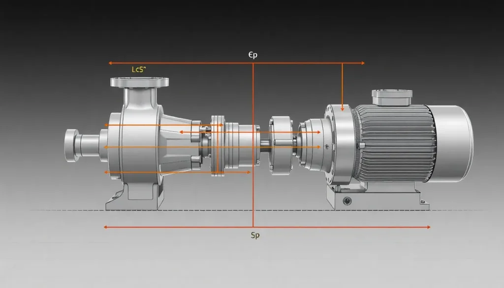
Short Answer
Key Formula / Key Facts Box
| Symbol | Meaning | US Unit | SI Unit | Plain‑English Restatement |
|---|---|---|---|---|
| δp | Parallel (linear) offset | mil (0.001 in) or mm | mm | How far the shafts are laterally displaced. |
| θ | Angular misalignment | minutes (′) or degrees (°) | radians (rad) or mrad | Angle between the two shaft axes. |
| L | Distance between measurement points (usually coupling face to face) | in | mm | Length over which the offset is measured. |
| δa | Angular‑equivalent offset | mil | mm | Linear offset that would produce the same angular error over length L (δa = L·tanθ). |
Core relationship: θ = arctan(δp / L) (radians) or θ (minutes) = (δp (mil) / L (in)) × 1000. This converts a measured parallel offset into an angular misalignment for any shaft length.
Overview — What It Is and Why It Matters
Shaft alignment is the process of ensuring that the rotational axes of a pump and its driver motor are coincident within prescribed tolerances. Misalignment introduces bending stresses, uneven bearing loads, and excessive vibration, which accelerate bearing wear, seal leakage, and coupling failure. In centrifugal pumps, even a 0.001 in (0.025 mm) parallel offset can raise bearing temperature by 10 °F (5.5 °C) and reduce efficiency by up to 1 %.
Industry standards—such as ANSI/AGMA 9001‑2020 and ISO 10816—define acceptable limits based on shaft speed, bearing type, and coupling design. Meeting these limits preserves pump life, lowers maintenance costs, and protects downstream process equipment from vibration‑induced damage.
The Method — Derivation and Variants
The geometric basis of alignment stems from right‑triangle trigonometry. For a shaft of length L with a measured lateral offset δp, the angular deviation θ is:
θ = arctan(δp / L) (radians). For small angles (θ < 5°), tanθ ≈ θ, so the relationship simplifies to θ ≈ δp / L.
Two common variants are used in practice:
- Soft‑Coupling Method (laser or dial indicator): Measures parallel offset at two points (usually at the coupling faces) and computes angular error via the core relationship.
- Hard‑Coupling Method (geometric or “straight‑edge” technique): Aligns the coupling faces directly, then checks for parallelism; the angular component is inferred from the measured parallel offset and the known distance between the measurement points.
US‑customary form (mil/inch):
θ (minutes) = (δp (mil) / L (in)) × 1000
SI form (mm/mm):
θ (mrad) = (δp (mm) / L (mm)) × 1000
Constants (1000) convert the ratio into minutes of arc or milliradians, the units most commonly quoted in alignment specifications.
Worked Example
Example 1 – US Units
A 24‑in (2 ft) center‑to‑center distance between a 1800 rpm pump and its motor is measured with a dial indicator. The parallel offset at the motor side is 0.002 in (2 mil). Compute the angular misalignment in minutes.
- Convert distance to inches: L = 24 in.
- Apply the US‑customary formula: θ = (δp / L) × 1000 = (2 mil / 24 in) × 1000 = 0.0833 × 1000 ≈ 83 minutes.
Result: 83 minutes (≈ 1.4°). This is within the typical 1° (60 minutes) tolerance for flexible couplings at 1800 rpm, indicating the alignment is marginal and may need a fine adjustment.
Example 2 – SI Units
A horizontal pump‑motor set has a shaft centre distance of 600 mm. A laser tracker reads a parallel offset of 0.15 mm. Determine the angular misalignment in milliradians.
- L = 600 mm, δp = 0.15 mm.
- θ = (δp / L) × 1000 = (0.15 / 600) × 1000 = 0.00025 × 1000 = 0.25 mrad.
Result: 0.25 mrad (≈ 0.86°). For a rigid disc coupling at 1500 rpm, the recommended limit is ≤ 0.3 mrad, so the installation meets the tolerance.
Calculator
For quick conversions, use the online shaft‑alignment calculator: http://pumpcalcs.com/calculators/shaft-alignment/.
Reference Values & Typical Ranges
| Application | Speed (rpm) | Typical Parallel Tolerance | Typical Angular Tolerance |
|---|---|---|---|
| Flexible (elastomeric) coupling | ≤ 1500 | 0.001 in (0.025 mm) | 1° (60 min) / 0.3 mrad |
| Disc (rigid) coupling | ≤ 3000 | 0.0005 in (0.013 mm) | 0.5° (30 min) / 0.15 mrad |
| Gear or jaw coupling | ≤ 2000 | 0.0015 in (0.038 mm) | 1.5° (90 min) / 0.45 mrad |
Source: ANSI/AGMA 9001‑2020, ISO 10816‑3.
Application Guidance
- Pre‑alignment: Verify that the baseplates are level and that bolt torque follows the equipment manual. Uneven torque skews the datum plane and defeats even the best measurement technique.
- Measurement technique: Use a laser shaft‑alignment system for high‑speed units (> 2000 rpm) because it reduces operator error and provides repeatability within ±0.001 in.
- Temperature effects: Allow the pump, motor, and coupling to reach normal operating temperature before final alignment. Thermal expansion can change L by up to 0.5 mm for a 1‑m shaft at 100 °C.
- Re‑alignment schedule: Record baseline alignment data. Re‑check after major maintenance, bearing replacement, or any event that could shift the baseplates.
- Coupling selection: Choose a coupling whose tolerance envelope comfortably exceeds the measured misalignment. Over‑specifying a flexible coupling for a rigid system may hide alignment problems that later cause premature bearing wear.
Common Mistakes, Limits & Safety Notes
- Mixing units – Applying the US formula with SI measurements (or vice‑versa) produces errors up to 100 ×.
- Neglecting angular component – Relying solely on parallel offset ignores the larger effect of angular misalignment on bearing loads.
- Measuring at only one point – Alignment must be verified at both coupling faces; a single‑point check can hide a “scissor” condition.
- Over‑tightening bolts – Excessive torque can deform the baseplate, introducing hidden misalignment and cracking the flange.
- Skipping thermal stabilization – Aligning a cold pump can lead to drift once the machine warms up, requiring costly rework.
- Using inappropriate tolerance – Applying flexible‑coupling tolerances to a rigid disc coupling may cause premature bearing failure.
- Ignoring vibration limits – Misalignment often manifests as high‑frequency vibration; failure to monitor vibration can mask a developing problem.
- Safety hazard – Misaligned shafts can cause sudden coupling disengagement, exposing rotating parts. Always lock out/tag out before adjustment.
FAQ
What is the difference between parallel and angular misalignment?
Parallel (or linear) misalignment is the lateral distance between the two shaft axes measured at a single plane, usually expressed in mils or millimetres. Angular misalignment is the tilt angle between the axes, expressed in minutes of arc or milliradians, and is derived from the parallel offset divided by the distance between measurement points.
Can I use a dial indicator for high‑speed (> 3000 rpm) pumps?
Dial indicators can be used, but their repeatability drops at very high speeds and thermal growth becomes significant. For speeds above 3000 rpm, laser alignment systems are recommended because they provide faster data acquisition and higher accuracy without the need for multiple probe setups.
How often should shaft alignment be checked?
A baseline check is performed after initial installation. Re‑check after any major maintenance (bearing replacement, motor rewinding, baseplate work), after a significant temperature change, and during routine preventive‑maintenance intervals—typically every 6‑12 months for critical service.
What are acceptable misalignment limits for a gear coupling?
Gear couplings generally allow up to 0.0015 in (0.038 mm) parallel offset and 1.5° (90 min) angular misalignment for speeds up to 2000 rpm. Always verify the manufacturer’s specific limits, as material and tooth design can affect tolerance.
Why does misalignment cause premature bearing wear?
Misalignment creates uneven load distribution on bearing races, leading to localized stress concentrations. This accelerates fatigue, generates excess heat, and can cause premature spalling or corrosion, especially in high‑speed or high‑load applications.
Is it safe to tighten coupling bolts before confirming alignment?
No. Bolts should be tightened to the torque specified by the manufacturer only after the shafts are aligned. Over‑tightening can deform the coupling or baseplate, introducing hidden misalignment and creating a safety hazard if the coupling fails under load.
What role does thermal growth play in alignment?
As the pump and motor heat up, their shafts expand. For a steel shaft, the expansion is roughly 12 µm per °C per meter. This can shift the alignment by several mils, so final alignment should be performed at operating temperature or allowances should be made in the alignment plan.
Can I correct misalignment by shimming only one side of the motor?
Shimming a single side can correct parallel offset but may introduce angular error on the opposite side. The preferred method is to adjust both motor and pump baseplates symmetrically, using turn‑buckle or adjustable mounts to address both parallel and angular components.


Leave a Reply