
Short Answer
Key Formula / Key Facts Box
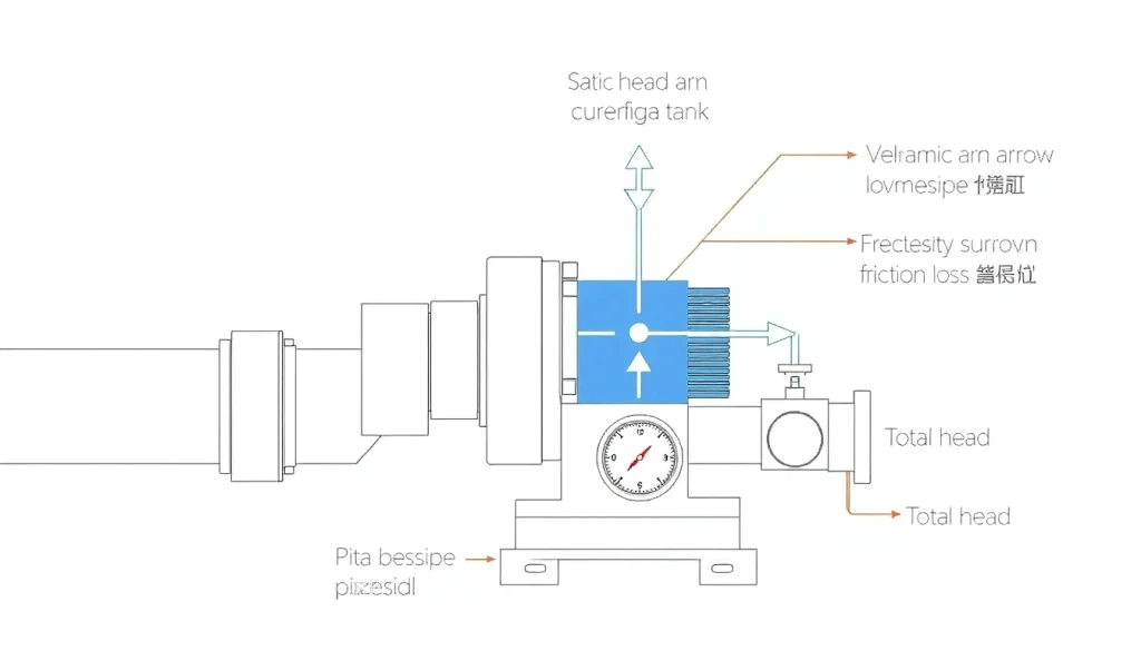
Total Head (H_T): H_T = H_S + H_D = frac{p_s – p_a}{gamma} + frac{v^2}{2g} + z
| Symbol | Meaning | US Unit | SI Unit | Plain English |
|---|---|---|---|---|
| H_T | Total head | ft | m | Overall energy per unit weight the pump must supply. |
| H_S | Static head | ft | m | Elevation difference between suction and discharge. |
| H_D | Dynamic head | ft | m | Energy to overcome velocity and friction losses. |
| p_s | Discharge pressure | psi | Pa | Pressure at the pump outlet. |
| p_a | Atmospheric pressure | psi | Pa | Reference pressure at the suction inlet. |
| gamma | Specific weight (rho g) | lb/ft³ | N/m³ | Weight of the fluid per unit volume. |
| v | Mean fluid velocity | ft/s | m/s | Speed of flow in the pipe. |
| g | Acceleration due to gravity | 32.174 ft/s² | 9.80665 m/s² | Constant that relates weight to mass. |
| z | Elevation above datum | ft | m | Vertical height of the discharge point. |
Overview — What It Is and Why It Matters
In hydraulic engineering, “head” is a measure of energy per unit weight of a fluid, expressed as the height of a column of liquid that would produce the same pressure. Pump head tells us how much energy a pump must add to move fluid from the suction side to the discharge side. It is split into two conceptual parts:
- Static head – the pure elevation change, independent of flow speed.
- Dynamic head – the kinetic and frictional energy required to accelerate the fluid and overcome pipe losses.
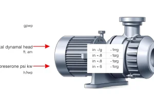
The sum of these, called total head (sometimes total dynamic head, TDH), is the key parameter used in pump selection, motor sizing, and system performance prediction. An underestimate leads to cavitation, insufficient flow, and premature wear; an over‑estimate wastes capital and energy.
The Method — Derivation and Variants
The Bernoulli equation, applied between a point just upstream of the pump inlet (1) and a point downstream of the pump outlet (2), is the starting point:
p_1/gamma + v_1^2/(2g) + z_1 + H_T = p_2/gamma + v_2^2/(2g) + z_2 + h_f
Rearranging, the pump head H_T becomes:
H_T = (p_2 – p_1)/gamma + (v_2^2 – v_1^2)/(2g) + (z_2 – z_1) + h_f
In most pump‑system analyses the inlet and outlet velocities are assumed equal (v_1 ≈ v_2) and the minor loss term h_f is grouped with the dynamic head. This yields the compact form shown in the Key Facts Box.
Two variants are common:
- US‑customary form uses ft, psi, and lb/ft³. The conversion factor 144 in²/ft² is embedded when converting pressure to head: H (ft) = (p (psi) × 144) / γ (lb/ft³).
- SI form directly uses Pa and N/m³, so H (m) = (p (Pa) – p_a) / (ρ g).
Both are algebraically identical; the choice depends on the units used in the project specification.
Worked Example
Example 1 – US Units
A 2‑in. centrifugal pump must deliver 500 gpm of water from a 20‑ft deep sump to a tank 45 ft above the sump. The discharge pipe is 4 in. schedule 40 steel with a friction loss of 5 ft per 100 ft. The total pipe length is 150 ft. Atmospheric pressure is 14.7 psi. Determine the total head required.
- Convert flow to ft³/s: 500 gpm × 1 ft³/7.4805 gal = 66.9 ft³/min = 1.115 ft³/s.
- Velocity in 4‑in. pipe (area A = π·(4/12/2)² = 0.349 ft²): v = Q/A = 1.115 / 0.349 = 3.19 ft/s.
- Dynamic head (velocity head + friction):
- Velocity head = v²/(2g) = 3.19²/(2·32.174) = 0.158 ft.
- Friction loss = (5 ft/100 ft) × 150 ft = 7.5 ft.
- Dynamic head H_D = 0.158 + 7.5 ≈ 7.66 ft.
- Static head = elevation difference = 45 ft (discharge) – (‑20 ft) = 65 ft.
- Total head H_T = H_S + H_D = 65 ft + 7.66 ft ≈ 72.7 ft.
The selected pump must be rated for at least 73 ft of head at 500 gpm.
Example 2 – SI Units
A chemical plant needs to move 0.12 m³/s of a 900 kg/m³ liquid from a basin 6 m below ground to a processing tank 18 m above the basin. The discharge line is 150 mm PVC, 80 m long, with a Darcy‑Weisbach loss of 0.02 m per 10 m. Atmospheric pressure is 101.3 kPa. Compute total head.
- Pipe area A = π·(0.15/2)² = 0.0177 m². Velocity v = Q/A = 0.12 / 0.0177 = 6.78 m/s.
- Velocity head = v²/(2g) = 6.78²/(2·9.80665) = 2.34 m.
- Friction loss = (0.02 m/10 m) × 80 m = 0.16 m.
- Dynamic head H_D = 2.34 m + 0.16 m = 2.50 m.
- Static head = 18 m (elevation) + 6 m (suction below datum) = 24 m.
- Total head H_T = 24 m + 2.50 m = 26.5 m.
A pump capable of ≥27 m head at 0.12 m³/s is required.
Calculator
For quick conversion and verification, use an online total dynamic head calculator: http://pumpcalcs.com/calculators/total-dynamic-head/
Reference Values & Typical Ranges
- Domestic water‑supply pumps: 10 – 60 ft (3 – 18 m) total head.
- Industrial circulation loops: 30 – 200 ft (9 – 60 m) depending on elevation and pipe length.
- High‑rise building booster systems: 100 – 400 ft (30 – 120 m) static head dominates.
- Typical friction loss coefficients for common pipe materials (per 100 ft):
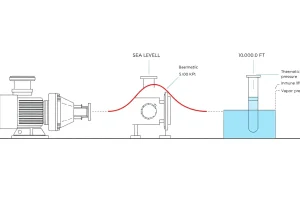
Material Size (in.) Loss (ft/100 ft) Steel (SCH40) 4 5.0 PVC (Schedule 40) 4 3.2 Stainless (SCH80) 2 8.7 - Maximum advisable suction lift for water at 68 °F (20 °C) without cavitation: ≈ 10.5 ft (3.2 m) at sea level.
Application Guidance
When sizing a pump, start with the static head, which is a fixed geometry term. Add dynamic head calculated from the anticipated flow rate, pipe diameter, roughness, and fittings. Remember to include:
- Minor losses (valves, elbows) – usually 0.5 – 2 % of total head.
- Net Positive Suction Head Required (NPSHR) of the selected pump; ensure NPSHA (available) exceeds NPSHR by at least 10 % to avoid cavitation.
- Temperature‑dependent density changes; for non‑water liquids, use the actual ρ in the specific‑weight term.
- Altitude corrections – specific weight γ decreases with elevation, increasing required head.
Field engineers often apply a 5‑10 % safety margin to the calculated total head to accommodate future flow‑rate changes or fouling.
Common Mistakes, Limits & Safety Notes
- Unit mix‑up: Substituting psi directly into a foot‑head equation without the 144 conversion factor yields a head error of > 10 ×.
- Neglecting velocity head: At high flow rates, the v²/2g term can contribute > 5 % of total head; omitting it leads to undersized pumps.
- Assuming zero friction: Even smooth PVC incurs measurable loss; ignoring it overestimates efficiency.
- Using water density for oil: Specific weight for light oils can be 30‑40 % lower than water, inflating calculated head.
- Overlooking elevation datum: Mixing absolute elevations with relative lifts causes systematic head errors.
- Exceeding pump curve limits: Selecting a pump that operates far left of its Best Efficiency Point (BEP) reduces lifespan.
- Safety – Cavitation: Insufficient suction head causes vapor bubbles that implode, damaging impellers and seals.
- Altitude effect: At 5,000 ft, γ drops ≈ 15 %; recalculate head to avoid motor overload.
FAQ
Why do engineers talk about head instead of pressure?
Head converts pressure into an equivalent height of fluid, which directly relates to the energy a pump must impart. It simplifies comparison across liquids of different densities and aligns with the Bernoulli equation used in pump design.
Can I ignore velocity head for low‑flow applications?
If the fluid velocity is below about 2 ft/s (0.6 m/s), the velocity head contributes less than 0.1 ft (0.03 m) and can be omitted without appreciable error. For higher flow rates, include it.
How does altitude affect total head calculations?
Higher altitude reduces atmospheric pressure and the fluid's specific weight, effectively increasing the required pump head for the same discharge pressure. Apply the local γ value or add an altitude correction factor (≈ 0.15 % per 1,000 ft).
What is the difference between total head and total dynamic head?
Total head includes the static elevation component, whereas total dynamic head (TDH) usually refers to static head plus friction and velocity losses, excluding any pressure already present at the suction inlet.
Do I need to consider pipe material when calculating head loss?
Yes. Different materials have distinct roughness coefficients, which affect the Darcy‑Weisbach friction factor. Steel, PVC, and stainless steel each have standard loss tables that should be consulted.
Is it acceptable to add a safety factor to the pump head?
A 5‑10 % safety margin is standard practice to accommodate future flow changes, fouling, and minor modeling inaccuracies. Excessive margins, however, can lead to oversized pumps and higher energy costs.
Leave a Reply