Short Answer
Key Formula / Key Facts Box
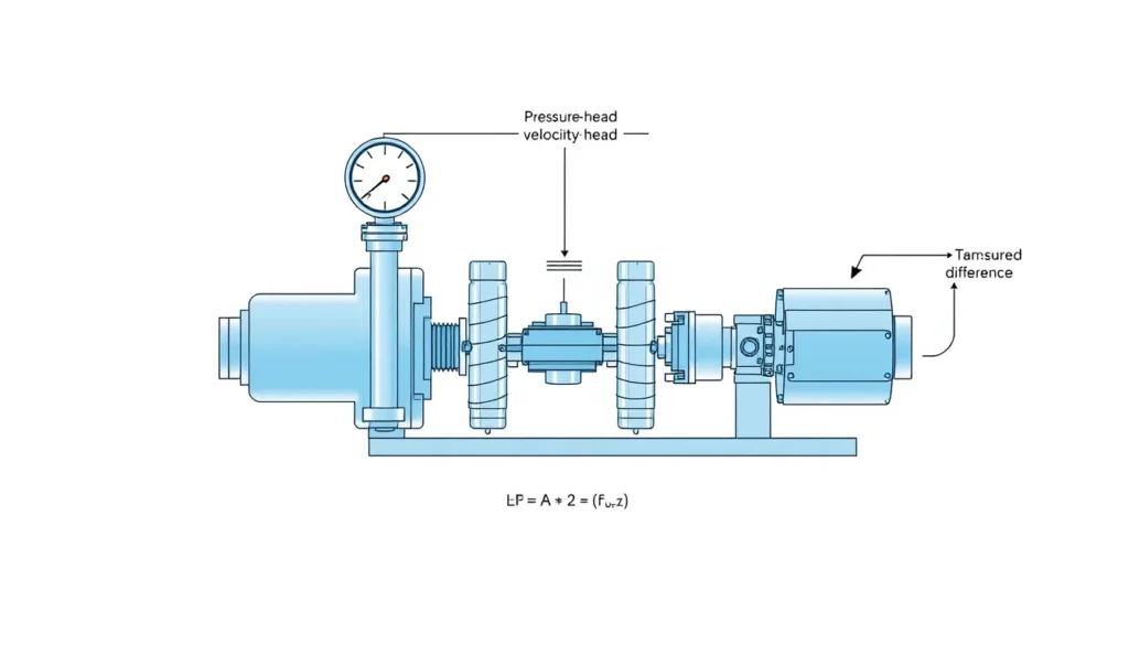
Governing formula: Hp = (Pd − Ps)/γ + (zd − zs) + (Vd2 − Vs2)/(2g) + hf,s + hf,d
US customary form: Hp (ft) = 2.31(Pd − Ps)/SG + (zd − zs) + (Vd2 − Vs2)/(2g) + hf
SI form: Hp (m) = (Pd − Ps)/(ρg) + (zd − zs) + (Vd2 − Vs2)/(2g) + hf
| Symbol | Meaning | US unit | SI unit |
|---|---|---|---|
| Hp | Pump head (total dynamic head) | ft of fluid | m of fluid |
| Pd, Ps | Discharge and suction gauge pressures at their measurement reference points | psig | Pa gauge |
| γ | Specific weight of pumped fluid, γ = SG·γw = ρg | lb/ft³ | N/m³ |
| zd, zs | Elevations of the discharge and suction gauge centers or chosen reference points from a common datum | ft | m |
| Vd, Vs | Mean velocities in the discharge and suction pipes at the measurement sections | ft/s | m/s |
| g | Gravitational acceleration | 32.174 ft/s² | 9.80665 m/s² |
| hf,s, hf,d | Friction head between each gauge/reference point and the pump flange; set to zero when gauges are effectively at the flanges | ft | m |
Plain-English restatement: Convert the pressure difference to head, add the vertical difference between the two gauge centers from a common datum, add the velocity-head difference, and add any remote-line friction corrections before comparing the result with the pump curve.

Overview — What It Is and Why It Matters
Correcting pump head calculations for gauge elevation differences means putting every pressure reading on the same hydraulic datum before subtracting suction from discharge. A pressure gauge reports the pressure at its sensing element, not necessarily at the pump flange, the pipe centerline, or the other gauge. If the discharge gauge is 2 ft above the suction gauge, the fluid column between them contributes about 0.87 psi of water-equivalent pressure, or about 2 ft of head. Ignoring that vertical offset biases total dynamic head (TDH) and can make a healthy pump look wrongly sized or a marginal pump look acceptable.
This article uses the common encyclopedic scope: steady, incompressible liquid flow in a pump circuit, with pressure gauges installed in liquid-filled lines and readings corrected to their gauge centers or to the pump flanges. The physical intuition is simple. Pressure head P/γ, elevation head z, and velocity head V²/(2g) are three forms of mechanical energy per unit weight. Pump head is the difference between the discharge and suction energy levels. A gauge only sees pressure; its elevation must be supplied by the person calculating head.
The engineering relevance is high during commissioning, performance testing, troubleshooting, and energy audits. A published vertical-turbine example shows the consequence: a discharge gauge reading of 30 psig was first treated as about 70 ft of head, but the 13 ft elevation difference between the gauge and the water level changed the corrected head to about 83 ft. When the pump curve was re-read, the apparent flow moved from roughly 20,000 gpm to about 9,000 gpm. That is not a rounding error; it changes the diagnosis of the pump operating point and can hide operation far from best efficiency point.
The Method — Derivation and Variants
Start with the steady, incompressible energy equation written per unit weight. At the suction measurement section s, Es = Ps/γ + zs + Vs2/(2g). At the discharge measurement section d, Ed = Pd/γ + zd + Vd2/(2g). By definition, pump head is Ed − Es, plus friction corrections when the gauges are remote from the pump flanges. Expanding the terms gives the governing equation shown above.
The elevation term zd − zs is the gauge-elevation correction when Pd and Ps are the actual gauge readings and zd and zs are the centers of those gauges measured from one common datum. If a reading has already been corrected to a tapping or flange, use the tapping or flange elevation instead and do not apply the gauge-center correction again. This is the most common source of double counting.
For a liquid-filled, static sensing line, the pressure at a tapping is ptap = pgauge + γ(zgauge − ztap). A gauge above the tapping has a positive height difference and reads lower than the tapping; add γΔz to the gauge reading to obtain tapping pressure. A gauge below the tapping reads higher; the correction is subtractive. Trapped gas, diaphragm seals, a different fill liquid, or an uncertain reference point invalidate this simple liquid-column model and require the instrument manufacturer method.
The US customary and SI forms are directly equivalent, but constants differ. In US units, 2.31 ft of water per psi is the reciprocal of the water pressure gradient of about 0.433 psi/ft. For a liquid with specific gravity SG, use 2.31/SG ft per psi, or 0.433·SG psi/ft. In SI units, convert pressure to pascals and divide by ρg; if pressure is in bar, multiply by 100,000 Pa/bar first. Standard gravity is 32.174 ft/s² or 9.80665 m/s². The main variants are: flange-gauge tests, where hf is normally zero; remote-gauge tests, where friction between the gauge and flange must be added; tank-suction tests, where the suction reference is the tank liquid surface with zero velocity and tank gas pressure; and NPSH calculations, where absolute pressure is required and gauge-elevation corrections must not be mixed with TDH corrections.
| Term | US customary | SI |
|---|---|---|
| Pressure head | 2.31(Pd − Ps)/SG | (Pd − Ps)/(ρg) |
| Elevation head | zd − zs | zd − zs |
| Velocity head | (Vd2 − Vs2)/(2g) | (Vd2 − Vs2)/(2g) |
| Remote-line friction | hf,s + hf,d | hf,s + hf,d |
Worked Example
US customary example. A horizontal centrifugal pump handles a fluid with SG = 0.95 at 800 gpm. The discharge gauge reads 45 psig at zd = 12.0 ft. The suction gauge reads −4 psig at zs = 3.0 ft. The discharge pipe inside diameter is 6.0 in and the suction pipe inside diameter is 8.0 in. Assume the gauges are effectively at the pump flanges, so hf = 0. Use g = 32.174 ft/s² and V = 0.4085Q/D² with Q in gpm and D in inches. Vd = 0.4085 × 800/6² = 9.08 ft/s. Vs = 0.4085 × 800/8² = 5.11 ft/s. The velocity-head difference is (9.08² − 5.11²)/(2 × 32.174) = 0.88 ft. The pressure difference is 45 − (−4) = 49 psi. Pressure head is 2.31 × 49/0.95 = 119.15 ft. The elevation correction is 12.0 − 3.0 = 9.0 ft. Therefore Hp = 119.15 + 9.0 + 0.88 = 129.0 ft. If the 9 ft elevation correction were omitted, the result would be about 120.0 ft, nearly 7% low.
SI example. A pump handles a fluid with SG = 1.10, so ρ = 1100 kg/m³, at Q = 0.060 m³/s. The discharge gauge reads 3.20 bar at zd = 2.10 m. The suction gauge reads −0.35 bar at zs = 0.80 m. The discharge pipe inside diameter is 0.150 m and the suction pipe inside diameter is 0.200 m. Use g = 9.81 m/s². Vd = 0.060/(π × 0.150²/4) = 3.40 m/s. Vs = 0.060/(π × 0.200²/4) = 1.91 m/s. The velocity-head difference is (3.40² − 1.91²)/(2 × 9.81) = 0.40 m. The pressure difference is 3.20 − (−0.35) = 3.55 bar = 355,000 Pa. Pressure head is 355,000/(1100 × 9.81) = 32.9 m. The elevation correction is 2.10 − 0.80 = 1.30 m. Therefore Hp = 32.9 + 1.30 + 0.40 = 34.6 m. If the elevation correction were omitted, the result would be about 33.3 m, roughly 4% low.
Calculator
Use a field-ready total dynamic head calculator such as the Total Dynamic Head Calculator or the MEASUR Pump Head Calculator to combine pressure, elevation, velocity, and line-loss terms. Enter gauge pressures in the same reference, psig or Pa gauge, elevations from one datum, and pipe inside diameters at the measurement sections.
Reference Values & Typical Ranges
Use these values as checks, not substitutes for project-specific fluid properties and instrument calibration.
| Quantity | Typical value or range | Field note |
|---|---|---|
| Water pressure-to-head conversion | 1 psi ≈ 2.31 ft of water; 1 ft of water ≈ 0.433 psi | For SG other than 1, use 2.31/SG ft per psi or 0.433·SG psi/ft. |
| SI water pressure-to-head conversion | 9.81 kPa per metre of water; 1 bar ≈ 10.2 m of water | Use exact ρg for non-water fluids or high-accuracy work. |
| Common gauge-elevation differences | 0–3 ft (0–1 m) on many horizontal pumps; 10 ft+ possible on vertical turbines and some split-case arrangements | Correct when Δz is significant relative to TDH or instrument uncertainty. |
| Velocity head at normal pipe velocities | About 0.1–1.5 ft (0.03–0.45 m) for many water pipes at 2–10 ft/s | Velocity head can be several feet at high velocity or small diameter. |
| Gauge accuracy | Typical industrial gauges about 1–2% of full scale | Compare the elevation correction with the gauge uncertainty before calling it negligible. |
| Specific gravity | Common process liquids about 0.7–1.5 | Use operating-temperature SG, not a nominal value. |
The MEASUR method uses a reference water specific weight of 62.316 lb/ft³ and a pressure gradient of about 0.43275 psi/ft. The Pumps & Systems vertical-turbine case shows a 13 ft gauge-elevation correction changing the interpreted flow from about 20,000 gpm to about 9,000 gpm. Deppmann notes that a 1 ft gauge-height difference may be minor on some pumps, while 2–3 ft on larger vertical-split-case pumps must be included. Pump Fundamentals gives the field equation with gauge-height correction and velocity head, and the Pump Handbook provides the broader hydraulic basis.
Application Guidance
In real systems, gauge elevation differences matter most when total head is low, gauge separation is large, or fluid specific gravity is far from water. A horizontal end-suction pump with suction and discharge tappings at nearly the same elevation may need only a small correction; a vertical turbine, vertical split-case, or inline pump with gauges at different levels can need several feet of head correction. Always define the datum, record the gauge-center elevation, and record whether the reading is at the gauge, tapping, or flange.
For pump selection, correct the measured point before plotting it on the curve. A lower-than-actual TDH makes flow appear higher and can hide operation far from the best efficiency point; a higher-than-actual TDH can make a properly operating pump appear deficient. In the field, use the same gauge for suction and discharge when practical to cancel calibration bias, but still correct elevation and velocity. For liquid-filled sensing lines, verify the line is full of the process liquid and free of trapped gas. For tank suction, use the tank liquid surface and gas pressure as the suction reference, with zero velocity at the surface. For remote gauges, add only the friction between the gauge and the pump flange, not the whole system friction. When specific gravity varies with temperature or concentration, use the operating density rather than a nominal value.
Common Mistakes, Limits & Safety Notes
- Treating pressure difference as TDH. Gauge pressure difference is only one term. Elevation and velocity head, plus remote-line friction where applicable, must be included.
- Reversing the elevation sign. A gauge above a tapping reads lower than the tapping; add the liquid-column correction to obtain tapping pressure. A gauge below the tapping requires a subtractive correction.
- Double counting the correction. Do not correct a reading to the tapping and then add the gauge-center elevation again. Use one consistent reference point.
- Using the wrong elevation. Measure to the gauge center, tapping, or flange as appropriate, and use one common vertical datum. The height is vertical, not the length of a looped sensing tube.
- Mixing gauge and absolute pressure. TDH usually uses gauge-pressure differences. NPSH available requires absolute pressure, with barometric and vapour-pressure corrections handled separately.
- Forgetting specific gravity. The 2.31 and 0.433 water constants must be adjusted for SG. A heavy brine and a light solvent do not produce the same head from the same psi.
- Ignoring velocity head. This is especially important when suction and discharge pipe diameters differ, when flow is high, or when a pump curve is being checked to a few percent.
- Assuming gauges are at the flanges. Remote gauges add friction, and a static sensing line with trapped gas or a diaphragm seal may invalidate the simple liquid-column correction.
- Using nominal density and rounding too early. Use operating ρ or SG, keep intermediate values, and round only the final result to the precision justified by the instruments.
- Safety. Do not open pressurized fittings, loosen gauge connections, or attempt correction measurements on a running pump without isolation, depressurization, and site safety procedures. Entrained gas, chemical exposure, and high-pressure lines can create serious hazards.
FAQ
Why must pump head be corrected for gauge elevation?
A pressure gauge reads pressure at its sensing center, not automatically at the pump flange or at the other gauge elevation. If discharge and suction gauges sit at different heights, the fluid column between them adds or subtracts hydrostatic head. Correcting to a common datum prevents the measured TDH from being biased before comparing it with the pump curve.
Does a higher gauge read lower pressure?
Yes for a static, liquid-filled line. If a gauge is above its tapping, the liquid column reduces the indicated pressure relative to the tapping by gamma times delta z. To get tapping pressure, add gamma times delta z to the gauge reading when the gauge is higher; subtract it when the gauge is lower. Trapped gas or seals invalidate this simple rule.
Is velocity head part of the elevation correction?
No. Velocity head is a separate energy term, Vd squared minus Vs squared divided by 2g. It becomes important when suction and discharge pipe diameters differ or velocities are high. Elevation correction handles only the vertical difference between measurement reference points. Use both terms in the complete TDH equation, not one in place of the other.
How do I correct pressure from a gauge to a tapping in feet?
For water, multiply vertical difference delta z in feet by 0.433 psi/ft, or by 0.433 times SG for another liquid. If the gauge is above the tapping, add that pressure to the gauge reading; if below, subtract. Alternatively, work in head: 1 psi of water equals about 2.31 ft; divide by SG for other liquids.
When can gauge elevation be ignored?
It can often be ignored only when delta z is very small relative to total head and within gauge uncertainty, such as a few inches on a high-head pump. It should not be ignored when gauges are on different levels, on vertical turbines or split-case pumps, or when the correction exceeds about 1 to 2 percent of TDH.
Should I use 2.31 or 0.433?
They are reciprocal water-column constants: 1 psi is about 2.31 ft of water, and 1 ft of water is about 0.433 psi. Use 2.31/SG for head from psi and 0.433 times SG for psi from head. These are approximations for water at ordinary temperatures; use exact density for high-accuracy work or non-water fluids.
What if gauges are not at the pump flanges?
Correct each reading to the flange or chosen reference point and add the friction loss between gauge and flange when it is significant. Do not count the same elevation correction twice. If the line is short and velocity is low, friction may be negligible; otherwise calculate it from the loss coefficient or measured differential.
How do I calculate pump head in SI units?
Use Hp equals Pd minus Ps divided by rho g, plus zd minus zs, plus Vd squared minus Vs squared divided by 2g, plus friction. Pressures are in pascals, densities in kg/m3, elevations in metres, velocities in m/s, and g as 9.81 m/s2. If pressures are in bar, multiply by 100,000 Pa/bar before dividing by rho g.
Why did my corrected head not land on the pump curve?
Check gauge calibration, common datum, pressure units, specific gravity, velocity-head calculation, and whether suction or discharge pressure is negative. Pump wear, entrained air, throttled valves, or unsteady flow can also shift the point. Correcting elevation is necessary but not sufficient; the full measurement chain must be consistent.
Can I use gauge elevation correction for a tank suction?
If the suction reference is the tank liquid surface, use the surface elevation and tank gas pressure, and set suction velocity to zero at the surface. Do not use a suction-pipe gauge elevation unless you are explicitly using that gauge reading. Then add suction-line friction from the tank to the pump flange.

Leave a Reply