
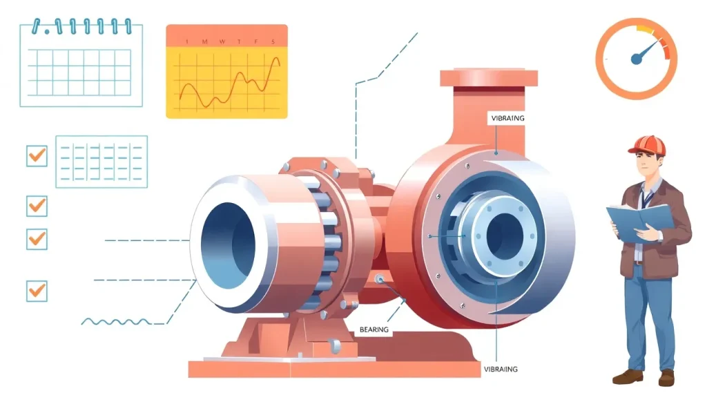
Short Answer
Key Formula / Key Facts Box
| Parameter | Meaning | Typical US Unit | Typical SI Unit |
|---|---|---|---|
| Inspection Interval | Time between routine visual and functional checks | Months | Months |
| Vibration Limit | Maximum allowable RMS velocity | in/s | mm/s |
| Bearing Temperature | Maximum safe bearing case temperature | °F | °C |
| Seal Leakage Rate | Acceptable leakage volume per hour | gph | L/h |
| Efficiency Degradation | Allowed drop in pump efficiency before overhaul | % | % |
Overview — What It Is and Why It Matters
Preventive maintenance (PM) for centrifugal pumps is a systematic set of inspections, measurements, and component replacements performed at predetermined intervals. The goal is to detect wear, corrosion, or imbalance before they cause a performance drop or catastrophic failure. Because centrifugal pumps convert mechanical energy to hydraulic energy via a rotating impeller, any deviation in clearance, bearing condition, or seal integrity directly affects flow, head, and efficiency. Missed PM can lead to increased energy consumption, unscheduled shutdowns, and costly repairs that exceed the nominal cost of the scheduled tasks.
The Method — Derivation and Variants
There is no single governing equation for a PM schedule; instead, the schedule derives from reliability‑centered maintenance (RCM) principles and industry standards such as API 610, ISO 5199, and ANSI/HI 9.6. The basic logic follows:
Next‑Maintenance‑Date = Last‑Maintenance‑Date + Recommended‑Interval
Recommended‑Interval is selected based on:
- Manufacturer’s warranty and service recommendations.
- Operating conditions (temperature, pressure, fluid aggressiveness).
- Historical failure data (MTBF, Weibull analysis).
- Regulatory requirements (e.g., ASME B31.3 for process plants).
Two common variants are:
- Time‑Based PM: Fixed calendar intervals (e.g., monthly visual inspection, annual bearing replacement).
- Condition‑Based PM: Intervals triggered by measured parameters (vibration exceeding 0.5 in/s RMS, bearing temperature > 200 °F, seal leakage > 0.5 gph).
Both approaches can be blended into a hybrid schedule that reduces unnecessary work while still guarding against hidden degradation.
Worked Example
Scenario A – US Customary Units
A 150 HP, 1800 rpm, single‑stage centrifugal pump operates in a petrochemical plant handling 800 gpm of 55 °F crude oil. The OEM recommends a visual inspection every 3 months, bearing temperature check every 1 month, and bearing replacement every 12 months. The plant records a bearing temperature of 190 °F and vibration of 0.4 in/s RMS.
- Determine next visual inspection:
Last inspection = 2026‑04‑01. Add 3 months →2026‑07‑01. - Check bearing temperature limit (200 °F). Current 190 °F < limit → no immediate action.
- Vibration limit is 0.5 in/s RMS; measured 0.4 in/s < limit → continue.
- Since bearing age is 10 months (<12 months), schedule bearing replacement at next 12‑month mark:
2026‑04‑01 + 12 months = 2027‑04‑01.
Scenario B – SI Units
The same pump is now specified in SI: 112 kW, 300 L/s, fluid temperature 12.8 °C. Manufacturer intervals are visual inspection every 90 days, bearing temperature check every 30 days, bearing replacement every 365 days. Current bearing temperature is 93 °C, vibration 12 mm/s RMS.
- Next visual inspection:
2026‑04‑01 + 90 days = 2026‑07‑01. - Temperature limit 93 °C (≈200 °F). Measured equals limit → schedule bearing temperature‑related maintenance within 7 days.
- Vibration limit 12.7 mm/s (≈0.5 in/s). Measured 12 mm/s < limit → acceptable.
- Bearing replacement due at
2026‑04‑01 + 365 days = 2027‑04‑01.
Both examples illustrate how the same logical steps apply regardless of unit system.
Calculator
For quick interval calculations, use an online maintenance‑interval calculator: http://pumpcalcs.com/calculators/maintenance-interval/
Reference Values & Typical Ranges
- Visual inspection interval: 1 – 6 months (API 610, Table 3).
- Vibration RMS limit for balanced impeller: 0.5 in/s (12.7 mm/s) (ISO 10816‑3).
- Bearing temperature limit (oil‑lubricated): 200 °F (93 °C) (ANSI/HI 9.6‑1).
- Mechanical seal leakage: ≤ 0.5 gph (≤ 0.2 L/h) for critical services (API 682).
- Efficiency degradation trigger: 5 % drop from rated efficiency (ASME B73.1).
Application Guidance
When building a PM schedule, start with the OEM’s baseline intervals and then adjust based on:
- Fluid aggressiveness – corrosive or abrasive fluids accelerate seal and impeller wear.
- Operating point – pumps frequently throttled near shut‑off experience higher radial forces and vibration.
- Environmental factors – ambient temperature, dust, and humidity affect bearing life.
- Historical data – use reliability logs to refine MTBF and shift intervals toward a risk‑based approach.
Document each task in a maintenance log, record measured values, and flag any trend that exceeds the “action limit.” Trend analysis software (e.g., PI System) can automatically generate work orders when limits are crossed.
Common Mistakes, Limits & Safety Notes
- Mixing US and SI units in the same calculation. Always convert before comparing limits; a 0.5 in/s vibration limit is 12.7 mm/s.
- Skipping vibration analysis. Visual checks alone cannot reveal bearing shaft misalignment or impeller imbalance.
- Over‑tightening mechanical seals. Excess preload can cause premature seal wear and higher leakage rates.
- Ignoring temperature trends. A steady rise of 5 °F per month often signals lubrication breakdown.
- Delaying bearing replacement until failure. Run‑to‑failure policies dramatically increase downtime and may violate safety regulations.
- Neglecting PPE and lock‑out/tag‑out. Maintenance on rotating equipment must follow OSHA 1910.147 to prevent accidental start‑up.
FAQ
How often should I inspect the pump bearings?
For most oil‑lubricated centrifugal pumps, a bearing temperature check is recommended monthly, with a full bearing inspection or replacement annually or sooner if temperature exceeds 200 °F (93 °C).
Can I extend the visual inspection interval if the pump runs smoothly?
While a smooth operation is a good sign, extending intervals without data can hide gradual wear. It is safer to follow the OEM’s minimum interval or use condition‑based monitoring to justify extensions.
What vibration level indicates an imminent bearing failure?
When RMS velocity rises above 0.7 in/s (≈18 mm/s) or shows a rapid upward trend over two consecutive measurements, it typically signals bearing degradation requiring immediate attention.
Is it necessary to shut down the pump for every maintenance task?
Not all tasks require a full shutdown. Minor visual inspections can be performed with the pump isolated and locked out, while bearing or seal replacements generally need a complete stop and lock‑out/tag‑out.
How does fluid temperature affect the maintenance schedule?
Higher fluid temperatures accelerate lubricant breakdown and seal wear, often prompting shorter inspection intervals and more frequent oil analysis.
What documentation is required for regulatory compliance?
Maintain a logbook or digital record that includes dates, performed tasks, measured values (vibration, temperature, leakage), personnel signatures, and any corrective actions; many codes (e.g., ASME B31.3) reference these records for audits.
Leave a Reply