Short Answer
Key Formula / Key Facts Box
Governing friction-loss formula: hf = f (L/D) (V2/(2g))
Flow form for a full circular pipe: hf = 8 f L Q2 / (π2 g D5)
| Symbol | Meaning | US unit | SI unit |
|---|---|---|---|
| hf | Friction head loss | ft | m |
| f | Darcy-Weisbach friction factor | dimensionless | dimensionless |
| L | Straight run length | ft | m |
| D | True inside diameter | ft | m |
| V | Mean flow velocity | ft/s | m/s |
| Q | Flow rate | gpm or ft3/s | m3/s |
| g | Gravitational acceleration | 32.174 ft/s2 | 9.80665 m/s2 |
Plain-English restatement: friction head rises with hose length and with velocity squared, and it falls very sharply as true inside diameter increases; rough, kinked, collapsed, or undersized layflat adds loss, while rigid pipe usually keeps a steadier bore but may add joints, elbows, and corrosion or scale.
| Key fact | Practical meaning |
|---|---|
| One-size reduction can roughly triple or nearly quadruple friction | At 420 gpm, published data cited for dewatering shows about 7.5 ft head loss per 100 ft in 4-inch layflat versus 27.8 ft per 100 ft in 3-inch layflat. |
| Length scales friction directly | Doubling the straight run roughly doubles straight-pipe friction head at the same flow and diameter. |
| Diameter dominates | In Darcy-Weisbach form, friction varies approximately with D5 at fixed flow, so small diameter errors create large head errors. |
| Velocity above about 5 ft/s is often marginal in layflat tables | Higher velocity increases friction, abrasion, and wear; manufacturer tables should be checked for the exact product. |
| Layflat can swell under pressure | One supplier notes swell up to 10 percent beyond uncharged diameter at maximum operating pressure, which changes flow area and hydraulic performance. |
| Total dynamic head is the sum | TDH = static lift + straight-line friction + minor losses from bends, valves, couplings, and reducers. |
Overview — What It Is and Why It Matters
In this article, layflat hose vs rigid pipe means the hydraulic comparison of temporary dewatering discharge lines: the hose or pipe that carries water away from a sump, cofferdam, flooded compound, construction pit, or emergency site. The scope is steady turbulent water flow in typical dewatering sizes, roughly 2 to 8 inches nominal, not suction hose design and not permanent municipal water mains.

A pump curve gives the head and flow a pump can produce, but the discharge line decides how much of that capability is actually available. The system consumes head through static lift, straight-run friction, and minor losses at bends, couplings, reducers, and valves. If the line is undersized, kinked, partly collapsed, or full of sharp bends, the system curve becomes steeper and the pump operating point moves to lower flow. The pump may sound normal while quietly delivering far less than the job requires.
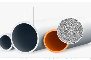
Layflat hose is attractive in dewatering because it is compact, fast to deploy, follows ground contours, and comes in long continuous lengths with fewer joints. Rigid pipe is attractive because it holds a fixed smooth bore, can be buried or supported, and often tolerates higher pressure and longer service life. The friction comparison is therefore not simply hose versus pipe; it is a comparison of true inside diameter, surface roughness, pressure expansion, kinks, joints, fittings, corrosion, scale, and installation quality.
The consequences of error are practical: a flooded excavation drains too slowly, a pump runs farther left on its curve and may overheat or consume excess power, fuel use rises, and temporary lines may burst or disconnect under pressure. Getting the friction loss right is a core part of pump selection and system design for dewatering.
The Method — Derivation and Variants
The standard starting point is the energy equation reduced to Darcy-Weisbach head loss. For a full circular conduit, the friction head is proportional to length, inversely proportional to diameter, and proportional to velocity squared. The universal form is hf = f (L/D) (V2/(2g)). In US customary units, the same equation is written with feet, feet per second, and g equal to 32.174 ft/s2; in SI units it uses metres, metres per second, and g equal to 9.80665 m/s2.
- US customary:
hf(ft) = f (L(ft)/D(ft)) [V(ft/s)]2 / (2 × 32.174 ft/s2) - SI:
hf(m) = f (L(m)/D(m)) [V(m/s)]2 / (2 × 9.80665 m/s2)
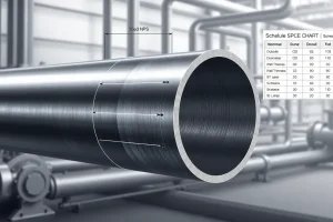
Because velocity equals flow divided by area, V = Q/A and A = πD2/4, substitution gives hf = 8 f L Q2 / (π2 g D5). This is why diameter is the most powerful sizing variable. A small reduction in true inside diameter can multiply friction several times at the same flow, especially when the pipe or hose is already near its velocity limit.
Minor losses are added separately. Each bend, valve, coupling, reducer, or inlet or outlet condition has a loss coefficient K, giving hm = K V2/(2g). Field calculations often convert minor losses into equivalent length of straight conduit, Leq = K D / f, so the total becomes straight length plus equivalent length. Published equivalent-length tables for rigid PVC and CPVC fittings are commonly used as a stand-in when dedicated layflat fitting data are unavailable, but the result should be treated as an estimate.
Hazen-Williams is another empirical variant widely used for water mains and rigid pipe. It is convenient for fixed-bore, long-term pipelines, but it is less suitable for layflat hose because the roughness coefficient is not constant when the hose wrinkles, swells, kinks, or partially collapses. For dewatering layflat, manufacturer friction-loss tables at the actual flow and nominal size are usually the best source. For rigid pipe, Darcy-Weisbach or Hazen-Williams can be used, with allowances for corrosion, scale, and joint losses. In both cases, the calculation must use true inside diameter, not merely nominal size.
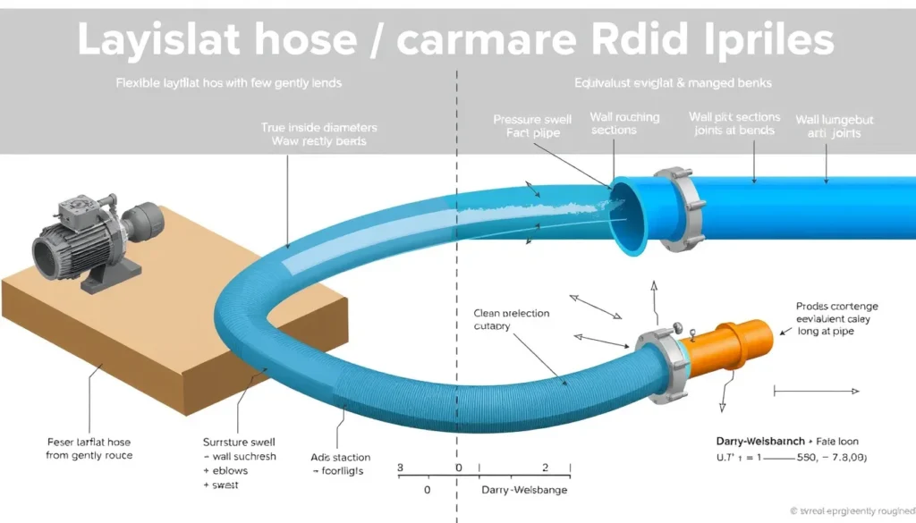
Layflat hose can have fewer joints than rigid pipe, which reduces some minor losses, and it can swell under pressure, which increases flow area and may reduce velocity and friction. However, layflat can also wrinkle at low pressure, crush at road crossings, kink at sharp bends, and behave worse than any clean published table if it is not fully inflated. Rigid pipe usually has a smoother, steadier bore, but it introduces more joints, elbows, and potential corrosion or scaling in long-term service.
Worked Example
US customary example. A flooded compound must be dewatered at 420 gpm to a soakaway 300 ft away, with 12 ft of static lift and two 90-degree bends around a vehicle track. A 4-inch class trash pump is rated to about 555 gpm and 92 ft maximum head. Published layflat data cited for this comparison gives 7.5 ft head loss per 100 ft for 4-inch hose and 27.8 ft per 100 ft for 3-inch hose at 420 gpm. Use 11.4 ft equivalent length for each 4-inch 90-degree bend and 7.9 ft for each 3-inch bend.
| Item | 4-inch layflat | 3-inch layflat |
|---|---|---|
| Straight-run friction | 300/100 × 7.5 = 22.5 ft | 300/100 × 27.8 = 83.4 ft |
| Two bends as equivalent length | 2 × 11.4 = 22.8 ft | 2 × 7.9 = 15.8 ft |
| Friction from bends | 22.8/100 × 7.5 = 1.7 ft | 15.8/100 × 27.8 = 4.4 ft |
| Static lift | 12.0 ft | 12.0 ft |
| Total dynamic head required | 22.5 + 1.7 + 12.0 = 36.2 ft | 83.4 + 4.4 + 12.0 = 99.8 ft |
The 4-inch line needs 36.2 ft, comfortably inside the pump maximum head of 92 ft. The 3-inch line needs 99.8 ft, which exceeds the pump maximum. The 3-inch system therefore cannot sustain 420 gpm; the operating point moves to lower flow, and the crew may wrongly blame the pump when the real problem is discharge-line friction.
SI example. Convert the same case: 420 gpm is about 95.3 m3/h, 300 ft is 91.4 m, and 12 ft is 3.66 m. The friction ratios are the same, 7.5 m per 100 m for 4-inch hose and 27.8 m per 100 m for 3-inch hose. The 4-inch straight loss is 91.4/100 × 7.5 = 6.86 m; bends add 6.95 m equivalent length, giving 0.52 m; static lift is 3.66 m; total is about 11.04 m. The 3-inch straight loss is 25.4 m; bends add 4.82 m equivalent length, giving 1.34 m; total is about 30.4 m. The pump maximum head is about 28.0 m, so the 3-inch line again exceeds the pump capability.
Calculator
For a quick check, use the online Total Dynamic Head Calculator. Enter the static lift, straight-run length, true inside diameter, flow rate, and minor-loss allowance. Compare the calculated total dynamic head with the pump curve at the target flow, not with the pump maximum flow printed on the nameplate. For layflat hose, cross-check the result against the hose manufacturer friction table because swell, kinks, and low-pressure wrinkling can shift actual performance.
Reference Values & Typical Ranges
Published values vary by product construction, liner, pressure, and flow. The following reference points are useful for preliminary comparisons and should be replaced by manufacturer data for final sizing.
| Condition | Typical value or rule | Source note |
|---|---|---|
| 4-inch layflat at 420 gpm | About 7.5 ft head per 100 ft; velocity about 10.6 ft/s | SLS dewatering hose article citing Midwest Hose data |
| 3-inch layflat at 420 gpm | About 27.8 ft head per 100 ft; velocity about 18.2 ft/s | SLS dewatering hose article citing Midwest Hose data |
| 6-inch vs 8-inch at 4200 gpm | About 70.8 vs 18.5 ft head per 100 ft | SLS dewatering hose article citing Midwest Hose data |
| 4-inch 90-degree bend | About 11.4 ft equivalent length | PVC and CPVC fitting data cited by SLS |
| 3-inch 90-degree bend | About 7.9 ft equivalent length | PVC and CPVC fitting data cited by SLS |
| Layflat velocity caution | Above about 5 ft/s is often marked marginal in layflat tables | Drip Depot layflat friction and velocity table |
| Layflat pressure swell | Up to 10 percent beyond uncharged diameter at maximum operating pressure | Pump Industry Magazine layflat hose feature |
| Temporary versus permanent service | Layflat is fast and compact but generally has higher head loss and is not for burial; rigid pipe is stronger and more stable for long-term service | Oxfam Distribution Manual; Pump Industry Magazine |
- Keep target total dynamic head at or below about 80 to 85 percent of the pump maximum head at the desired flow, leaving margin for fouling, kinks, and aging.
- Use true inside diameter and a manufacturer friction table for the actual layflat product; do not assume a nominal 4-inch hose matches a 4-inch rigid pipe.
- Add 10 to 20 percent margin for couplings, bends, partially inflated hose, debris, and field conditions when published minor-loss data are incomplete.
- Keep dewatering discharge velocity near or below about 5 ft/s (1.5 m/s) where practical, especially for abrasive water or long runs.
- Account for static lift separately; it does not change with hose size, but it consumes head that cannot be recovered by friction reduction.
Application Guidance
In real dewatering systems, layflat hose is often the right choice for temporary discharge because it can be laid quickly, follows contours, and reduces the number of joints. The hydraulic penalty is most noticeable on long runs, high flows, sharp bends, and lifted discharges. A practical response is to use a larger layflat size than a rigid-pipe comparison might suggest, keep the hose fully inflated, avoid sharp bends, protect road crossings, and use gradual transitions at the pump and discharge point.
Rigid pipe is preferable where the line will be buried, supported, exposed to high pressure, or kept in service for a long period. Its fixed bore makes friction prediction more stable, but joints, elbows, valves, corrosion, and scale must be included. In rehabilitation or permanent dewatering, a smooth rigid main may have lower life-cycle friction than a kinked layflat line, even if the layflat has a slightly larger nominal size. In temporary emergency work, layflat usually wins on deployment speed, but it still must be sized with the system curve in mind.
Selection implications are straightforward: compare the pump curve with the discharge system curve for each candidate size and material. If the target flow lies too far left on the pump curve, increase diameter, shorten the run, reduce bends, or split the flow into parallel lines. Check the actual discharge pressure or flow during commissioning; a pressure gauge near the pump and a flow measurement at the outlet reveal whether the installed line matches the calculation. Field judgment must also consider abrasion, chemical compatibility, UV exposure, traffic loading, and the consequences of a burst or disconnect.
Common Mistakes, Limits & Safety Notes
- Using pump rated flow without the system curve. A pump does not deliver its nameplate flow against an arbitrary discharge line; the operating point is where the pump curve meets the system curve.
- Comparing nominal sizes instead of true inside diameters. A 4-inch layflat hose, a 4-inch PVC pipe, and a 4-inch steel pipe may have different bores, especially when the hose is pressurized or partly inflated.
- Ignoring length and static lift. A line that works on a short flat run may fail on a long run or a lifted discharge because friction and elevation both consume head.
- Forgetting bends, couplings, reducers, and valves. Minor losses add up; two 4-inch 90-degree bends can add over 20 ft of equivalent length.
- Applying rigid-pipe roughness coefficients to layflat hose. Layflat performance changes with pressure, kinks, wrinkles, and swell; manufacturer tables are more reliable.
- Mixing units. Gpm with cubic feet per second, inches with feet, or psi with feet of head can produce large errors. Convert to a consistent unit set before calculating.
- Ignoring kinks, crushed sections, and partial collapse. A damaged or poorly laid layflat line can behave worse than any published table and may create dangerous backpressure.
- Exceeding safe velocity and pressure limits. High velocity increases abrasion and friction; overpressure can burst a hose or disconnect a coupling. Use the hose pressure rating and proper restraints.
- Using layflat for burial or permanent high-pressure service. Layflat is generally a temporary, above-ground solution; rigid pipe is preferred where strength, burial, and long service life are required.
- Skipping commissioning checks. Measure flow or pressure after installation. If the pump is far from its expected operating point, revisit diameter, length, lift, and fittings before changing the pump.
FAQ
Does layflat hose have more friction loss than rigid pipe?
It depends on true inside diameter, pressure, and condition. For the same nominal size and fully inflated layflat, friction can be similar to or somewhat higher than smooth rigid pipe because layflat may wrinkle, kink, or use a rougher liner. However, layflat often swells under pressure and has fewer joints. Use the manufacturer friction table rather than assuming nominal size alone.
How much head loss does 4-inch layflat hose have at 420 gpm?
Published layflat data cited for dewatering shows about 7.5 ft of head loss per 100 ft of 4-inch hose at 420 gpm, with velocity around 10.6 ft/s. A 3-inch hose at the same flow is about 27.8 ft per 100 ft. These values are product-specific and should be checked against your hose manufacturer table.
Can I use a smaller hose if the dewatering run is short?
Sometimes, but short runs still need a system-curve check. A one-size reduction can triple or nearly quadruple friction at the same flow. On a 50 ft run the extra head may be small; on a 300 ft run or with lift it can exceed the pump curve and cut flow sharply. Calculate TDH before deciding.
How do bends and fittings affect dewatering friction loss?
Every bend, coupling, reducer, and valve adds minor loss, often handled as equivalent length of straight hose. For example, a 4-inch 90-degree elbow may add about 11.4 ft of equivalent length, while a 3-inch elbow adds about 7.9 ft. Two bends can add 15 to 23 ft of equivalent length, so include them in TDH.
Why does my pump not reach rated flow with layflat hose?
The pump rated flow is available only when the discharge system uses less head than the pump can produce. Undersized hose, long runs, lift, kinks, and fittings raise total dynamic head and move the operating point to lower flow. Check actual inside diameter, hose length, elevation, bends, and the pump curve together.
Does layflat hose swelling reduce friction loss?
Layflat hose can swell up to about 10 percent beyond uncharged diameter at maximum operating pressure, which increases flow area and can reduce velocity and friction. The effect is pressure-dependent and is not a substitute for proper sizing. At low pressure the hose may be nearer its uncharged diameter, so use conservative manufacturer data.
What discharge velocity is too high for dewatering hose?
Many layflat friction tables flag velocities above about 5 ft/s as marginal, although this is not a universal limit. Higher velocity raises friction loss, abrasion, noise, and wear. For long runs or abrasive water, keep velocity near or below 5 ft/s (1.5 m/s) where practical and follow the hose manufacturer limits.
Should I use layflat hose or rigid pipe for a long dewatering discharge?
Use layflat for temporary, fast-deploying, contour-following discharge where a larger diameter can control friction. Use rigid pipe for permanent, buried, high-pressure, or stable-alignment service where smooth bore and strength matter. Many projects use layflat near the pump and rigid pipe for long mains, with transitions designed for minor losses.
How do I calculate total dynamic head for a dewatering line?
Add static lift, friction loss in straight hose or pipe, and minor losses from bends, valves, and fittings. Friction loss comes from the manufacturer table or Darcy-Weisbach. Keep units consistent: feet with gpm and inches requires conversion, or use SI metres with cubic metres per second. Compare total head to the pump curve at target flow.
Leave a Reply