Short Answer
Key Formula / Key Facts Box
Governing formula: Q = q / (ρ cp ΔT)
US customary shortcut: Qgpm = qBtu/h / (500 × ΔT°F)
SI shortcut: QL/s = qkW / (4.18 × ΔTK)
| Symbol | Meaning | US unit | SI unit |
|---|---|---|---|
| Q | Recirculating pump capacity | gpm | L/s |
| q | Standby heat loss in supply piping from heater to farthest fixture | Btu/h | kW |
| ρ | Water density | 8.33 lb/gal | ≈0.997 kg/L |
| cp | Specific heat of water | 1 Btu/(lb·°F) | 4.18 kJ/(kg·K) |
| ΔT | Allowable temperature drop at farthest fixture | °F | K |
| 500 | US conversion constant: 8.33 lb/gal × 60 min/h × 1 Btu/(lb·°F) | Btu/(gal·°F·h) | — |
Plain English: For a chosen allowable temperature drop, circulate enough water to carry away the pipe heat loss; in US units, each 500 Btu/h of heat loss per °F of drop requires about 1 gpm.

Overview — What It Is and Why It Matters
In this article, domestic hot water recirculation pump sizing from heat loss means calculating the recirculation flow required to offset standby heat loss in the supply piping between the water heater and the farthest fixture. The scope is the flow calculation and its immediate pump-selection consequences; detailed pipe stress, electrical design, and code compliance are separate tasks. A recirculation pump keeps hot water close to taps so that a fixture does not have to run cold water to the drain before hot water arrives.
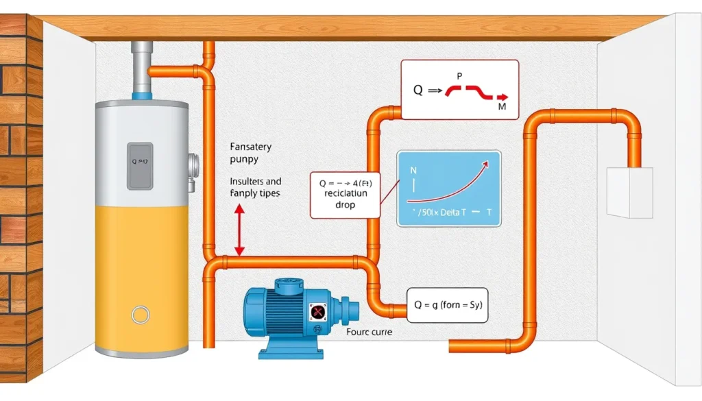
The physical idea is simple. When no fixtures are drawing water, the hot-water supply pipe loses heat to its surroundings. The recirculation pump moves water through the loop so that the temperature at the farthest fixture does not fall below the heater temperature by more than the design allowance, usually called ΔT. The heat-loss calculation answers one question: how much flow is needed? The piping and fitting calculation answers a second question: how much head must the pump develop at that flow? Both answers are required for a proper selection.
The consequence of error is significant. An undersized pump can leave the farthest fixture lukewarm and cause occupants to waste water while waiting. An oversized pump can create noise, erosion, excessive velocity, short cycling, and unnecessary energy use. Using the wrong ΔT or mixing US and SI units can shift the calculated flow by a factor of two or more, so the assumptions must be checked before the pump curve is consulted.
The Method — Derivation and Variants
Start with a steady-flow energy balance across the recirculating supply path. The heat lost by the pipe is carried by the water as sensible heat: q = ρ Q cp ΔT, where q is pipe heat loss, ρ is water density, Q is volumetric flow, cp is specific heat, and ΔT is the allowable temperature drop. Rearranging gives the governing sizing equation: Q = q / (ρ cp ΔT).
For US customary units, water weighs about 8.33 lb/gal and has a specific heat of about 1 Btu/(lb·°F). One gallon per minute therefore carries about 8.33 × 60 × 1 × ΔT = 500 × ΔT Btu/h. Thus Qgpm = qBtu/h / (500 × ΔT°F). For SI units, QL/s = qkW / (4.18 × ΔTK) for water density near 1 kg/L. If flow is required in m3/s, divide the L/s result by 1000.
| System | Equation | Constants and notes |
|---|---|---|
| US customary | Qgpm = qBtu/h / (500 × ΔT°F) | 500 ≈ 8.33 lb/gal × 60 min/h × 1 Btu/(lb·°F) |
| SI | QL/s = qkW / (4.18 × ΔTK) | 4.18 kJ/(kg·K); density near 1 kg/L |
| US, ΔT = 5°F | Qgpm = qBtu/h / 2500 | Common design simplification |
| US, ΔT = 10°F | Qgpm = qBtu/h / 5000 | Lower flow than 5°F case |
The heat loss q is usually obtained from ASHRAE tables, manufacturer data, or a recognized piping heat-loss chart. A common screening rule is 30 Btu/h per foot, or about 0.032 kW/m, but actual loss depends on pipe size, insulation, ambient temperature, and length. The return line downstream of the last fixture is generally excluded from the flow calculation because its heat loss does not reduce the temperature delivered to that fixture. The return line is still included in pump head because the pump must push water through it.
Once flow is known, calculate total dynamic head through the supply and return path: pipe friction, fittings, balancing valves, check valves, water heater, and any special components. For a fixed-Cv balancing valve, pressure drop in psi can be estimated from ΔP = (Qgpm/Cv)2; convert psi to feet of head using the fluid specific gravity. In multi-branch systems, sum the branch flows required to offset heat loss in each supply branch to its farthest fixture, and use balancing valves to distribute flow.
Worked Example
US customary example. A small apartment building has 120 ft of 3/4 in insulated copper supply piping from the water heater to the farthest fixture. A heat-loss table gives 1,800 Btu/h per 100 ft for this pipe and insulation. The owner accepts a 5°F temperature drop at the farthest fixture.
- Heat loss: q = 1,800 × 120/100 = 2,160 Btu/h.
- Required flow: Q = 2,160 / (500 × 5) = 2,160 / 2,500 = 0.864 gpm, rounded to 0.9 gpm.
- Return and fittings: assume 120 ft of 3/4 in copper return at 0.86 gpm has 1.2 ft/100 ft friction; pipe loss = 1.44 ft. Add check valve 1.0 ft, balancing valve 1.5 ft, heater 0.5 ft, and fittings 1.0 ft.
- Total head: 1.44 + 1.0 + 1.5 + 0.5 + 1.0 ≈ 5.4 ft.
Select a circulator that delivers about 0.9 gpm at 5.4 ft of head, and verify that the operating point is stable on the pump curve. The heat-loss calculation set the flow; the piping and valve losses set the head.
SI example. A commercial branch has a calculated supply-pipe heat loss of 0.60 kW and a design allowance of 2 K. Required flow is Q = 0.60 / (4.18 × 2) = 0.0718 L/s, or about 4.31 L/min. If the allowable drop were relaxed to 5 K, the flow would fall to Q = 0.60 / (4.18 × 5) = 0.0287 L/s, or about 1.72 L/min. With a calculated head of 1.2 m, select a pump for roughly 4.3 L/min at 1.2 m for the 2 K case. This example shows why the choice of ΔT must be deliberate.
Calculator
For the head side of the selection, use a total dynamic head calculator such as the PumpCalcs Total Dynamic Head Calculator and enter the recirculation flow, pipe lengths, fittings, valve losses, and heater losses. For the flow side, first calculate supply-pipe heat loss q, choose ΔT, then apply Q = q/(500 ΔT) in US units or Q = q/(4.18 ΔT) in SI. Always verify that the calculator or spreadsheet is using the same unit system as the heat-loss data and pump curve.
Reference Values & Typical Ranges
| Parameter | Typical value / range | Practical note |
|---|---|---|
| Design ΔT | 5–10°F (2–5 K); some designs use 10–20°F (5.6–11 K) | Lower ΔT requires higher flow. UpCodes recommends 5°F (2 K) for peak sufficiency; JMP cites 10–20°F in common designs. |
| Supply-pipe heat loss, small insulated copper | 1,600–2,000 Btu/h per 100 ft (0.015–0.019 kW/m) | Use ASHRAE or manufacturer tables for actual pipe, insulation, and ambient conditions. |
| Rule-of-thumb heat loss | 30 Btu/h per ft (0.032 kW/m) | Screening only; not a substitute for detailed heat-loss data. |
| Flow per 1,000 Btu/h | 0.4 gpm at ΔT = 5°F; 0.2 gpm at ΔT = 10°F | Useful for quick checks before formal calculation. |
| Typical small-system pump flow | 0.5–5 gpm (0.03–0.32 L/s) | Large multi-riser systems can be higher; sum branch heat losses. |
| Typical small-system head | A few feet to about 20 ft (0.6–6 m) | Verify with pipe, valve, check-valve, heater, and balancing-valve losses. |
Application Guidance
In real systems, the heat-loss calculation establishes the minimum recirculation flow. The pump must then be selected to meet that flow at the actual system head and to operate in a stable region of its curve. Small circulators are often used because the heat loss from small insulated domestic piping is modest, but long runs, uninsulated pipe, high ambient temperatures, and restrictive balancing valves can move the selection toward a larger pump.
- Multi-branch systems: balance each branch to its calculated flow; otherwise one riser may receive too much flow while another remains cold.
- Controls: use timers, aquastats, thermostatic balancing valves, or variable-speed control where appropriate to reduce pump runtime and energy use.
- Instantaneous heaters: a tankless or instantaneous water heater may have a minimum recirculation flow for stable temperature control; the pump may need to be selected for the greater of heat-loss flow and heater minimum flow. Steam-fired instantaneous heaters can require higher recirculation rates at light load.
- Field verification: measure the temperature drop at the farthest fixture and adjust balancing or pump speed. Excessive ΔT suggests insufficient flow, air, a restriction, or higher heat loss than assumed.
Insulation, pipe routing, and dead-leg length strongly influence heat loss. Shortening the supply path to the farthest fixture may reduce required flow more effectively than changing the pump. Hot water temperature and recirculation control also interact with scald prevention and pathogen-risk management, so final settings should comply with local plumbing codes and the owner’s water-management plan.
Common Mistakes, Limits & Safety Notes
- Using return-line heat loss to size flow. Return-line loss occurs downstream of the last fixture and does not determine the delivered temperature; it belongs in the head calculation, not the flow calculation.
- Sizing only on flow. A pump selected without total dynamic head may not deliver the calculated flow once pipe, fittings, check valves, balancing valves, and heater losses are included.
- Mixing unit systems. Using 500 with metric heat loss, or 4.18 with gpm and °F, produces grossly incorrect results.
- Choosing the wrong ΔT. A smaller allowable drop requires more flow; using 10°F when the design requires 5°F can undersize the pump.
- Over-relying on rule-of-thumb heat loss. The 30 Btu/h per foot value is useful for screening but ignores pipe size, insulation, and ambient conditions.
- Ignoring heater minimum flow or control-valve pressure drop. Tankless heaters and thermostatic balancing valves can govern the selection rather than the pipe heat loss alone.
- Oversizing the pump. Excess flow can cause noise, erosion, valve hunting, and energy waste without making hot water arrive meaningfully faster.
- Safety and code limits. Recirculation design must respect scald-prevention temperatures, potable-water materials, electrical safety, and local code requirements; it is not a substitute for a licensed plumbing or mechanical design review.
FAQ
How do I size a domestic hot water recirculation pump from heat loss?
First estimate standby heat loss q in the supply piping from the water heater to the farthest fixture. Choose an allowable temperature drop Delta T, usually 5-10 degrees F (2-5 K). Compute Q = q/(500 Delta T) in US units or Q = q/(4.18 Delta T) in SI. Then calculate total dynamic head through the return piping, valves, check valves, and heater, and select a pump meeting that flow and head.
What Delta T should I use for DHW recirculation?
Common design values are 5 degrees F (2 K) or 10 degrees F (5 K). A smaller Delta T gives more flow and better temperature at the farthest fixture but uses more pump energy. UpCodes recommends 5 degrees F for peak sufficiency, while many designers use 10 degrees F where comfort allows. Confirm the choice with the owner's criteria and local code.
Should I include return piping heat loss in the recirculation flow calculation?
No for the delivered-temperature calculation. The return line is downstream of the last fixture, so its heat loss does not reduce the temperature at that fixture. Return piping, however, adds friction and must be included in pump head. If the return serves other branches, balance those branches and include their heat losses where they affect delivered temperature.
What is the 500 factor in GPM = BTUh / (500 x Delta T)?
The factor 500 comes from water properties and time units: about 8.33 lb per gallon, 60 minutes per hour, and 1 Btu per pound per degree Fahrenheit. Multiplying 8.33 x 60 x 1 gives approximately 500 Btu/(gal-degree F-hour). It is valid for typical domestic water; the metric form uses 4.18 kJ/(kg-K) and density near 1 kg/L.
What if my water heater is tankless or instantaneous?
Tankless heaters often have a minimum recirculation flow for stable temperature control, and that minimum may exceed the heat-loss calculation. Steam-fired instantaneous heaters may require a larger recirculation rate at light load. Size the pump for the greater of the heat-loss flow and the heater minimum flow, then verify head and controls with the manufacturer.
Can I use the 30 Btu/h per foot rule of thumb?
Only for early screening. The 30 Btu/h per foot value, about 0.032 kW/m, is a common rule of thumb, but actual loss varies strongly with pipe diameter, insulation, ambient temperature, and length. Use ASHRAE or manufacturer heat-loss tables for final sizing, and document assumptions in the design.
Why does my recirculation pump run but hot water is still slow?
Possible causes include an undersized pump, air in the loop, a stuck check valve, a failed balancing valve, or a bypass/timer setting. Also check that the pump is actually moving water through the intended branch and that the return is not reversed. Measure Delta T at the farthest fixture; if it is excessive, flow is too low or heat loss is higher than assumed.
Does a bigger recirculation pump improve hot water delivery?
Not necessarily. Once the pump provides the design flow, a larger pump mainly adds pressure, noise, erosion risk, and energy use without making water arrive faster. Delivery speed is governed by flow and loop layout, not pump size alone. Select for the calculated flow and head, then balance the branches and set controls.
Leave a Reply