
Short Answer
Key Formula / Key Facts Box
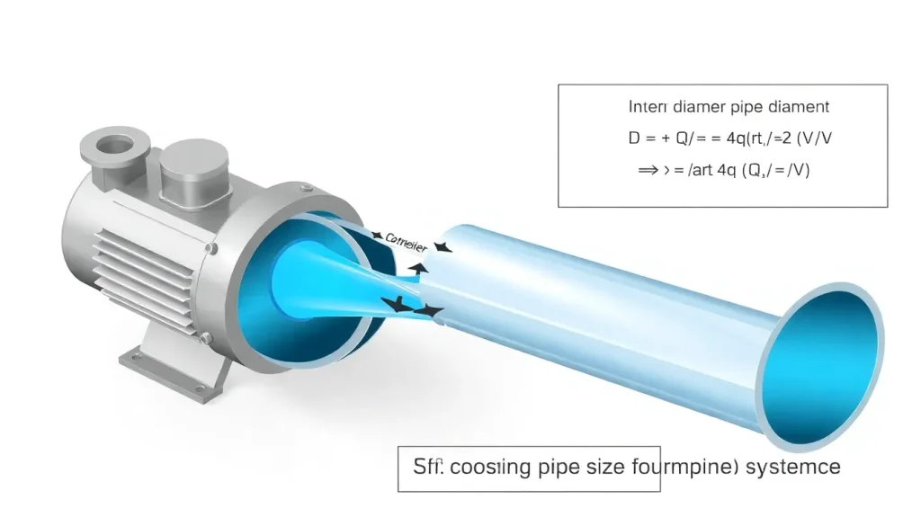
Pipe diameter (D) from flow (Q) and design velocity (V):
D = √[ (4 · Q) / (π · V) ]
| Symbol | Meaning | US Unit | SI Unit | Plain‑English |
|---|---|---|---|---|
| Q | Volumetric flow rate | gpm (gal/min) | m³/h | How much fluid moves per unit time. |
| V | Design velocity | ft/s | m/s | Target average speed of fluid in pipe. |
| D | Inside pipe diameter | inches | mm | Resulting pipe size to meet Q and V. |
| π | Constant 3.1416 | — | — | Geometric factor for circular cross‑section. |
Choose V between 3–8 ft/s (0.9–2.4 m/s) for water‑based systems to balance head loss and noise.
Overview — What It Is and Why It Matters
Pipe sizing links a pump’s hydraulic output to the downstream network. Selecting a diameter that is too small creates excessive friction loss, raising the required pump head, increasing energy consumption, and risking cavitation. An oversized pipe incurs unnecessary material cost, occupies space, and can cause low velocity problems such as sedimentation and poor temperature control. Correct sizing therefore influences pump selection, system efficiency, capital expense, and long‑term reliability.
The Method — Derivation and Variants
The governing relationship originates from the continuity equation for incompressible flow:
Q = A · V, where A = π D²/4
Re‑arranging for D gives the familiar formula shown above. In US customary units the constant 4/π ≈ 1.273 appears explicitly:
D(in) = 1.128 · √[ Q(gpm) / V(ft/s) ]
In SI units the same expression simplifies because the same numeric factor applies:
D(mm) = 1.128 · √[ Q(L/min) / V(m/s) ]
When dealing with viscous or non‑Newtonian fluids, a correction factor (k) may be introduced to adjust the design velocity:
D = √[ (4 · k · Q) / (π · V) ]
Typical k values: 1.0 for water, 0.85 for light oils, 0.70 for heavy oils.
Worked Example
Example 1 – US system (water)
- Required flow Q = 1500 gpm
- Select design velocity V = 6 ft/s (common for water)
Insert into US‑customary formula:
D = 1.128 · √[ 1500 / 6 ] = 1.128 · √250 = 1.128 · 15.81 ≈ 17.8 in
Standard pipe schedule 40 nominal size nearest to 17.8 in is 18 in (ID ≈ 17.3 in). Verify head loss with Darcy‑Weisbach; if within pump curve, accept the size.
Example 2 – SI system (light oil)
- Q = 0.09 m³/min (≈ 90 L/min)
- V = 1.5 m/s (lower velocity for oil)
- k = 0.85
Apply SI formula with correction factor:
D = √[ (4 · 0.85 · 0.09) / (π · 1.5) ] = √[ 0.306 / 4.712 ] = √0.0650 ≈ 0.255 m = 255 mm
Standard DN250 pipe (ID ≈ 242 mm) is the next commercial size; check that the resulting velocity (V_actual = Q/A) stays near 1.5 m/s.
Calculator
For quick sizing, use an online tool such as PumpCalcs Pipe‑Sizing Calculator. It accepts both US and SI inputs and outputs recommended pipe schedule.
Reference Values & Typical Ranges
- Design velocity for water: 3–8 ft/s (0.9–2.4 m/s)
- Design velocity for light oil: 2–5 ft/s (0.6–1.5 m/s)
- Design velocity for slurry: 1–3 ft/s (0.3–0.9 m/s)
- Maximum allowable head loss in distribution lines: 5–10 % of total dynamic head (TDH)
- Typical pipe schedule for water systems: Schedule 40 for diameters up to 24 in (610 mm)
- Recommended minimum Reynolds number for turbulent flow: Re > 4000 to ensure predictable friction factor
Sources: ANSI/HI 9.6‑1‑2020, ISO 9906:2012, Pump Handbook (Karassik et al., 2020).
Application Guidance
When integrating the pipe size into a pump selection loop, follow these steps:
- Define required flow (Q) and total dynamic head (TDH) from process data.
- Pick an initial design velocity based on fluid type and noise considerations.
- Calculate preliminary diameter (D) using the formula.
- Select the nearest commercial pipe size and schedule; compute actual velocity and friction loss with the Darcy‑Weisbach equation.
- If head loss exceeds 5–10 % of TDH, increase diameter and repeat.
- Check that the resulting velocity does not fall below 0.5 ft/s (0.15 m/s) for water, to avoid sedimentation.
- Confirm that the pipe’s pressure rating exceeds the pump’s discharge pressure plus static head.
Field engineers often adjust the velocity range by ±1 ft/s to accommodate space constraints or future capacity upgrades.
Common Mistakes, Limits & Safety Notes
- Unit mismatch: Plugging Q in L/min while using V in ft/s yields an incorrect D. Always keep units consistent.
- Ignoring fluid viscosity: Using water‑based velocities for heavy oils leads to excessive pressure drop.
- Over‑reliance on nominal size: Nominal pipe size is not the actual ID; verify the schedule’s internal diameter.
- Neglecting future flow increase: Design for peak demand plus 10‑15 % margin to avoid later pipe replacement.
- Under‑estimating head loss: Friction factor varies with Reynolds number and roughness; use the Colebrook‑White equation for accurate values.
- Safety oversight: Ensure pipe rating exceeds maximum working pressure (MWP) by at least 1.5× to accommodate transients.
- Leaving low velocity unchecked: Velocities < 0.5 ft/s can cause sediment buildup, especially in cooling water loops.
FAQ
What design velocity should I use for a chilled‑water loop?
For chilled‑water systems a common practice is 4–6 ft/s (1.2–1.8 m/s) to keep noise low while limiting friction loss. Adjust upward if pipe length is very short, or downward if the loop includes many bends.
Can I use the same pipe size for both the suction and discharge sides of a pump?
Not always. The suction side often requires a larger diameter to keep NPSH high and to avoid cavitation, especially for low‑flow, high‑head pumps. The discharge side can be sized based on the calculated friction loss and TDH.
How does fluid viscosity affect the pipe‑size calculation?
Viscosity does not appear in the continuity‑based diameter formula, but it influences the allowable design velocity and the friction factor. More viscous fluids need lower velocities and may require a larger pipe to keep head loss within limits.
Is it acceptable to size a pipe using the nominal diameter instead of the internal diameter?
No. Nominal size is a naming convention; the actual internal diameter varies with schedule. Always use the schedule‑specific ID when applying the flow‑velocity equation, otherwise the resulting velocity will be inaccurate.
What safety factor should I apply to pipe pressure ratings?
Industry guidelines recommend a pressure safety factor of at least 1.5× the maximum expected operating pressure, accounting for pressure spikes, thermal expansion, and corrosion allowance.
Should I consider future capacity upgrades when selecting pipe size?
Yes. It is good practice to add a 10–15 % flow margin to accommodate future plant expansions or process changes, which can prevent costly pipe replacements later.
How do I convert the formula for gallons per minute to liters per second?
First convert Q to L/min (1 gpm ≈ 3.785 L/min) or directly to L/s (divide by 60). Then use the SI version of the formula D(mm)=1.128·√[Q(L/min)/V(m/s)]. The numeric constant remains the same because the unit conversion is built into the constant.
Why does low velocity in a pipe cause sediment buildup?
When velocity falls below about 0.5 ft/s (0.15 m/s) the upward lift force on particles becomes insufficient to keep them suspended, allowing heavier solids to settle on the pipe wall, which can lead to blockage and reduced heat transfer.


Leave a Reply