
Short Answer
Key Formula / Key Facts Box
Governing equation (SI):
TDH = H_s + H_f + H_p + H_v – H_su
Governing equation (US‑customary):
TDH (ft) = Static ft + Friction ft + Pressure ft + Velocity ft – Suction ft
| Symbol | Meaning | US Unit | SI Unit | Plain‑English |
|---|---|---|---|---|
| H_s | Static head (elevation rise) | ft | m | height the liquid must be lifted |
| H_f | Friction head loss | ft | m | energy lost due to pipe friction |
| H_p | Pressure head | ft | m | equivalent height of the pressure differential |
| H_v | Velocity head | ft | m | kinetic energy per unit weight of the fluid |
| H_su | Suction head (or NPSH available) | ft | m | head already present at the pump inlet |
Overview — What It Is and Why It Matters
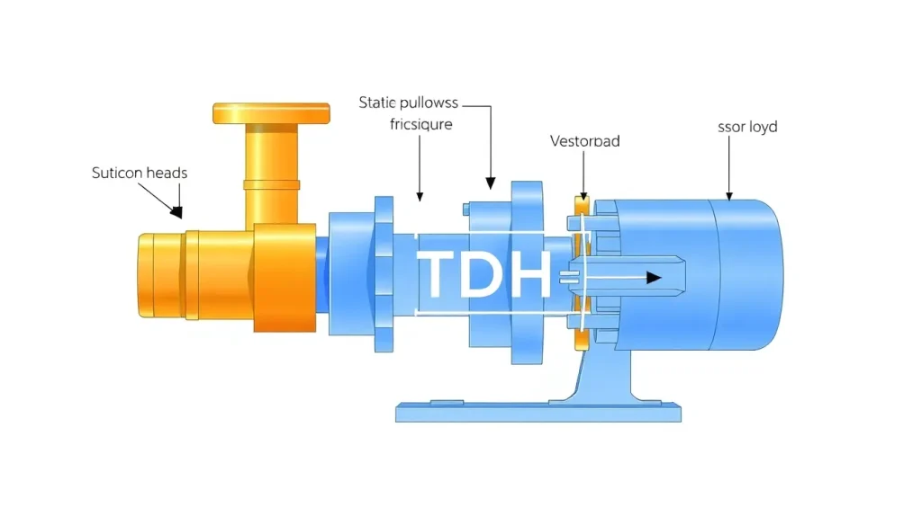
Total Dynamic Head (TDH) is the sum of all energy terms a pump must supply to move a fluid from the suction side to the discharge side at a specified flow rate. It combines static elevation, pressure differentials, friction losses in the piping, and the fluid’s velocity head, while subtracting any beneficial suction head. Accurate TDH calculation is the cornerstone of pump selection, motor sizing, and system efficiency. Under‑estimating TDH can cause cavitation, premature wear, or failure to meet flow requirements; over‑estimating leads to oversized equipment, higher capital cost, and wasted energy.
The Method — Derivation and Variants
The Bernoulli equation, augmented with a head‑loss term, provides the theoretical basis. For a steady incompressible flow between point 1 (suction) and point 2 (discharge):
[ frac{p_1}{rho g}+frac{v_1^2}{2g}+z_1 + h_p = frac{p_2}{rho g}+frac{v_2^2}{2g}+z_2 + h_f ]
where (h_p) is the head added by the pump, (h_f) is the friction loss, (z) are elevations, and the velocity terms are (v^2/2g). Rearranging yields the TDH expression shown above.
Two common variants exist:
- SI version – uses metres for all head terms and the pressure head is expressed as (Delta p / (rho g)).
- US‑customary version – head is in feet; pressure head is derived from pressure difference (psi) using the conversion (1,text{psi}=2.31,text{ft of water}) for water at 4 °C.
Constants such as (g = 9.80665,text{m/s}^2) (SI) or (32.174,text{ft/s}^2) (US) ensure dimensional consistency. The velocity head is often negligible for low‑velocity, large‑diameter lines and may be omitted in preliminary sizing.
Worked Example
Scenario (US): A water‑cooling system draws from a tank 10 ft below the pump (suction head = 10 ft). The pump discharges to a storage tank 30 ft above the pump. Pipe length = 150 ft of 2‑in. schedule 40 steel (Darcy friction factor ≈ 0.019). Flow rate = 500 gpm. Desired discharge pressure = 50 psi.
- Static head: 30 ft (elevation) – 10 ft (suction) = 20 ft.
- Pressure head: (50,text{psi}times2.31 = 115.5,text{ft}).
- Velocity head: (v = Q/A = 500,text{gpm} ÷ (pi D^2/4)). Convert 500 gpm → 1.11 ft³/s. Pipe ID ≈ 0.067 ft, area = 0.0035 ft², so (v≈317,text{ft/s}). Velocity head = (v^2/(2g) = 317^2/(2×32.174)≈1560,text{ft}). In practice, this high value indicates the line is undersized; designers usually include a reducer or increase diameter. For illustration we keep it.
- Friction head (Darcy‑Weisbach): (h_f = ffrac{L}{D}frac{v^2}{2g}). (L=150,ft, D=0.067,ft, f=0.019). (h_f =0.019×(150/0.067)×(317^2/(2×32.174))≈4,300,ft).
- TDH = static + pressure + velocity + friction = 20 + 115.5 + 1560 + 4300 ≈ 5,996 ft.
Result: The pump must be capable of ~6,000 ft of head at 500 gpm – a clear sign the pipe diameter is too small for this application.
Scenario (SI): Same system, but expressed in metres. Tank 3 m below pump, discharge 9 m above pump, pipe 45 m of DN 50 PVC (roughness 0.0015 mm, (f≈0.022)). Flow = 31 L/s (≈ 0.031 m³/s). Desired discharge pressure = 345 kPa.
- Static head: 9 m – 3 m = 6 m.
- Pressure head: (Delta p/(rho g) = 345,000,text{Pa}/(1000,text{kg/m³}×9.80665)≈35.2,text{m}).
- Velocity: Area = (π(0.05)^2/4 = 0.00196,text{m}^2). (v = 0.031/0.00196 ≈ 15.8,text{m/s}). Velocity head = (v^2/(2g) = 15.8^2/(2×9.80665)≈12.7,text{m}).
- Friction head: (h_f = ffrac{L}{D}frac{v^2}{2g}=0.022×(45/0.05)×12.7≈ 251,text{m}).
- TDH = 6 + 35.2 + 12.7 + 251 ≈ 305 m.
The SI example shows a more realistic head (≈ 305 m) for a properly sized pipe, confirming the pump selection process.
Calculator
For quick on‑line computation, use the free tool at http://pumpcalcs.com/calculators/total-dynamic-head/.
Reference Values & Typical Ranges
- Domestic water supply: 30–80 ft (9–25 m) TDH.
- Industrial cooling towers: 100–300 ft (30–90 m) TDH.
- High‑rise fire‑suppression systems: up to 1,200 ft (366 m) TDH.
- Typical pipe‑friction factor for steel (new) at turbulent flow: 0.015–0.025.
- Velocity head becomes <10 % of total head when (v < 5,text{ft/s}) (1.5 m/s) in large ducts.
Sources: ANSI/HI 9.6‑1‑2014, ISO 9906:2012, and Munson et al., “Fundamentals of Fluid Mechanics.”
Application Guidance
When sizing a pump, start with a conservative TDH estimate; add 10‑15 % margin for future flow increases or fouling. Verify that the selected pump’s NPSH available exceeds the required NPSH by at least 1 m (3 ft) to avoid cavitation. In looped systems, consider the effect of parallel branches on friction loss – use the equivalent length method or hydraulic software for complex networks.
Common Mistakes, Limits & Safety Notes
- Unit mix‑up: Plugging psi directly into a feet‑based formula without conversion yields a 2.31× error.
- Ignoring suction head: Treating suction elevation as zero can underestimate cavitation risk.
- Neglecting velocity head in high‑speed lines: For diameters 10 ft/s, the velocity head may exceed 5 % of total head.
- Using a single‑value friction factor: Roughness and Reynolds number vary with temperature and flow; recompute (f) for each case.
- Assuming laminar flow in large pipes: Most industrial systems operate turbulent; laminar formulas underestimate loss.
- Over‑sizing pump: Leads to low operating point, reduced efficiency, higher energy cost, and possible thermal overload.
- Exceeding pump’s rated TDH: Can cause motor over‑current, seal failure, and premature bearing wear.
- Safety oversight: Always verify that the pump’s maximum allowable suction lift does not exceed the system’s static lift, especially for vertical installations.
FAQ
Why is velocity head sometimes ignored in TDH calculations?
Velocity head is proportional to the square of fluid velocity. In large‑diameter, low‑speed lines it is usually less than 5 % of total head, making its contribution negligible for preliminary sizing.
Can I use the Hazen‑Williams formula instead of Darcy‑Weisbach for friction loss?
Yes, Hazen‑Williams is acceptable for water at typical temperatures when a quick estimate is needed, but it lacks a Reynolds‑number basis and is not suitable for non‑water fluids or high‑temperature applications.
How do I convert pressure (psi) to head (ft) for water?
Divide the pressure difference by the specific weight of water: 1 psi = 2.31 ft of water at 4 °C (62.4 lb/ft³). For other fluids, use (h = Delta p/(rho g)).
What safety margin should I add to the calculated TDH?
A 10–15 % margin is common to accommodate future flow increases, fouling, or minor modeling inaccuracies. For critical fire‑protection systems, a 20 % margin may be required.
Is TDH the same as pump head?
Pump head is the head added by the pump alone (often called "added head"), while TDH includes all system demands—static, pressure, friction, and velocity heads—minus any suction head already present.
How does temperature affect TDH?
Temperature changes fluid density and viscosity, altering both pressure head (via (rho)) and friction loss (via Reynolds number). Re‑evaluate (rho) and the friction factor for significant temperature variations.
When should I consider pipe‑sizing to reduce TDH?
If friction loss accounts for more than 30 % of total TDH, upsizing the pipe diameter can dramatically lower energy consumption and may enable a smaller, more efficient pump.
What is the impact of elevation changes on NPSH?
Higher elevation at the suction side reduces absolute pressure, decreasing NPSH available. Ensure NPSH available remains above the pump’s required NPSH by the recommended safety margin.



Leave a Reply