
Short Answer
Key Formula / Key Facts Box
Governing relationship for a direct-drive centrifugal pump on a near-fixed system curve: Q(t) ≈ Q_ref × [P_PV(t) / P_ref]1/3, with P_PV(t) ≈ η_sys × A × G(t) × (1 − L).
This article uses the most common encyclopedic scope: a battery-free, directly coupled photovoltaic (PV) pumping system in which motor-pump speed follows available solar power. Battery-buffered, grid-tied, and diesel-hybrid systems are mentioned only for comparison.
| Symbol | Meaning | US unit | SI unit |
|---|---|---|---|
| Q(t) | Instantaneous pump flow | gpm | m³/h or m³/s |
| P_PV(t) | PV electrical power at time t | hp or kW | kW |
| G(t) | Plane-of-array irradiance | Btu/(h·ft²) | W/m² |
| A | Array area | ft² | m² |
| η_sys | System efficiency from irradiance to pump shaft | dimensionless | dimensionless |
| L | Loss fraction for soiling, temperature, wiring, mismatch | dimensionless | dimensionless |
| Q_ref, P_ref | Reference flow and electrical power at a rated operating point | gpm, hp or kW | m³/h, kW |
| H | Total dynamic head | ft | m |
| N | Pump rotational speed | rpm | min⁻¹ |
Plain-English restatement: if available solar power falls by half, a centrifugal pump on a fixed system curve does not produce half flow; it produces roughly 0.51/3 = 0.79 of its reference flow, until it reaches the minimum power needed to keep turning and lifting water.
Overview — What It Is and Why It Matters
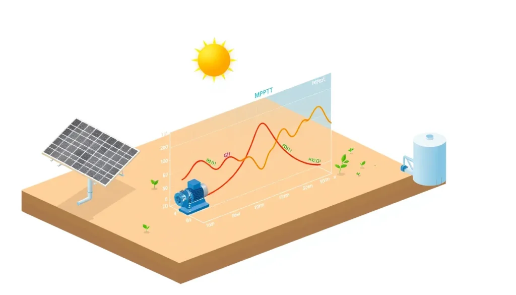
A direct-drive solar pump converts sunlight into water flow without a battery between the array and the motor. The array makes DC power, an MPPT controller or inverter tracks the array’s maximum power point, and the motor-pump set turns at whatever speed can be supported by the available power. When irradiance rises, the pump speeds up; when a cloud passes, it slows down; when irradiance falls below the minimum starting power, it stops. The water tank, not a battery, is normally the energy buffer.
The flow therefore changes throughout the day because two relationships are coupled. First, PV power follows solar irradiance, temperature, soiling, and inverter or MPPT behavior. Second, a centrifugal pump’s flow, head, and shaft power follow the affinity laws as speed changes. FAO describes stand-alone direct-irrigation systems as starting in the morning when solar output exceeds the minimum power required by the pump, running while sufficient irradiation is available, and stopping before sunset when output falls below that threshold; flow changes with solar irradiation during the day. RPS Solar Pumps describes the same field behavior as a morning ramp-up, a midday plateau, and an afternoon taper, with clouds, smoke, and dirty panels causing additional variation.

The engineering consequences are practical. If a designer assumes rated flow for 24 hours, daily volume can be overestimated by a factor of four or more. If an irrigation system is sized only for midday flow, low-light hours may deliver non-uniform pressure. If the pump is oversized relative to the array, it may never start or may operate only briefly near noon. If the array is oversized without checking pump maximum speed, extra power may not produce extra flow. Understanding why direct-drive solar pump flow changes throughout the day is therefore central to pump selection, array sizing, storage planning, and operating schedules.
The Method — Derivation and Variants
Step 1 — PV power from irradiance. At a given moment, the array’s DC power can be approximated as P_PV(t) = P_STC × [G(t) / G_STC] × η_derate, where P_STC is the array rating at standard test conditions, G_STC is 1000 W/m², and η_derate accounts for temperature, soiling, wiring, mismatch, and controller losses. Equivalently, P_PV(t) = η_sys × A × G(t) × (1 − L).
Step 2 — Shaft power. The motor and controller deliver P_shaft = η_drive × P_PV. Some of the electrical power becomes heat in the motor, controller, and cable; only the remainder reaches the pump shaft.
Step 3 — Hydraulic power. The water power is P_hyd = ρ g Q H in SI units. In US customary units, P_hyd = Q × H × SG / 3960, where P_hyd is in horsepower, Q is in gpm, H is in ft, and SG is specific gravity; for water SG = 1. The pump shaft power is P_shaft = P_hyd / η_p, where η_p is pump efficiency at the operating point.
Step 4 — Affinity laws and flow. For a geometrically similar centrifugal pump, Q ∝ N, H ∝ N², and P_shaft ∝ N³. If the system curve is approximately fixed and efficiency is roughly constant, eliminating speed gives Q ∝ P_shaft1/3, and therefore Q(t) / Q_ref ≈ [P_PV(t) / P_ref]1/3. This cube-root relationship is why flow changes less dramatically than power at high irradiance, but it also explains why flow collapses quickly near the minimum operating power.
| Relationship | US customary form | SI form | When it applies |
|---|---|---|---|
| Hydraulic power | hp = Q(gpm) × H(ft) × SG / 3960 | P_hyd = ρ g Q H | Any water pump |
| PV power | P_PV = P_STC × (G/G_STC) × η_derate | P_PV = η_sys A G (1 − L) | PV array at a given irradiance |
| Affinity flow | Q2 = Q1 × (N2/N1) | Q2 = Q1 × (N2/N1) | Centrifugal pump, similar speed change |
| Combined flow | Q ≈ Q_ref × (P/P_ref)1/3 | Q ≈ Q_ref × (P/P_ref)1/3 | Centrifugal pump, fixed system curve, constant efficiency |
| Positive-displacement flow | Q ≈ Q_ref × (N/N_ref) | Q ≈ Q_ref × (N/N_ref) | High-head positive-displacement pump; speed directly controls flow |
The cube-root variant is a useful first estimate for centrifugal pumps, but it is not universal. A system with large static head may show a steeper drop in flow at low irradiance because the pump must first overcome lift before useful flow begins. A positive-displacement pump behaves differently: flow is more nearly proportional to speed, and torque and pressure limits matter more. MPPT controllers improve energy harvest by holding the array near its maximum power point, but they do not eliminate irradiance-driven flow changes. Suehrcke, Appelbaum, and Reshef showed that pump similarity laws can be applied to variable-speed centrifugal pump performance in PV systems, with solar radiation and pipeline characteristics jointly determining flow.
Worked Example
Example 1 — SI units, centrifugal direct-drive pump. A 3.0 kWp array feeds an MPPT controller and a centrifugal pump. Assume η_sys = 0.75, a rated point of Q_ref = 12 m³/h at H = 30 m, and P_ref = 2.25 kW electrical. At the rated point, the hydraulic power is P_hyd = 1000 × 9.81 × (12/3600) × 30 = 981 W. With pump efficiency 0.55 and drive efficiency 0.85, the electrical input is about 981 / (0.55 × 0.85) = 2098 W, consistent with the assumed reference.
At G = 600 W/m²: P_PV = 0.75 × 3.0 kW × (600/1000) = 1.35 kW. The power ratio is 1.35 / 2.25 = 0.600. The estimated flow is Q = 12 × 0.6001/3 = 12 × 0.843 = 10.1 m³/h. At G = 900 W/m²: P_PV = 2.025 kW, ratio = 0.900, and Q = 12 × 0.9001/3 = 11.6 m³/h. At G = 300 W/m²: P_PV = 0.675 kW, ratio = 0.300, and Q = 12 × 0.3001/3 = 8.0 m³/h, although the pump may stop if this is below its minimum operating power. If the site has 5 effective peak sun hours at the reference point, daily volume is roughly 12 m³/h × 5 h = 60 m³/day before cloud and soiling derating.
Example 2 — US customary units, centrifugal direct-drive pump. A 4.0 kWp array feeds a pump rated at Q_ref = 50 gpm and H = 100 ft, with P_ref = 2.0 kW electrical and η_sys = 0.75. Check the hydraulic power: P_hyd = 50 × 100 / 3960 = 1.26 hp for water. With pump efficiency 0.55 and drive efficiency 0.85, electrical input is 1.26 / (0.55 × 0.85) = 2.69 hp = 2.01 kW, consistent with the reference.
At G = 700 W/m²: P_PV = 0.75 × 4.0 × 0.7 = 2.1 kW. Ratio = 2.1 / 2.0 = 1.05. Q = 50 × 1.051/3 = 50 × 1.016 = 50.8 gpm. At G = 500 W/m²: P_PV = 1.5 kW, ratio = 0.75, and Q = 50 × 0.751/3 = 45.5 gpm. At G = 300 W/m²: P_PV = 0.9 kW, ratio = 0.45, and Q = 50 × 0.451/3 = 38.3 gpm, subject to the pump’s minimum-power cutoff. A 5-peak-sun-hour day at 50 gpm gives about 50 gpm × 60 min/h × 5 h = 15,000 gal/day reference volume.
Calculator
For hydraulic head, flow, and pump power estimates, use the PumpCalcs Total Dynamic Head calculator: http://pumpcalcs.com/calculators/total-dynamic-head/. Pair the result with local peak-sun-hour data, array derating, and the manufacturer’s pump curve. The calculator estimates hydraulic duty; it does not directly model PV irradiance, MPPT tracking, or motor speed limits.
Reference Values & Typical Ranges
| Parameter | Typical range or rule of thumb | Notes and sources |
|---|---|---|
| Effective full-power pumping hours | About 3–5.5 h/day; tropical sites near 5 h, humid seasons near 4 h, higher-latitude winter near 3–3.5 h | Trista Solar Pumps; FAO notes a 6–8 h solar operation window, but not all of it is at full power. |
| Plane-of-array irradiance | STC 1000 W/m²; clear noon often 800–1000 W/m²; thin cloud 400–700 W/m²; heavy overcast 100–300 W/m² | RPS Solar Pumps; Trista Solar Pumps. |
| System derating η_sys | About 0.60–0.80 from irradiance to pump shaft | Includes temperature, soiling, wiring, mismatch, MPPT, motor, and pump efficiency. |
| Cloud transient flow | Flow may fall to roughly 30–60% of prior value for minutes, then recover | Trista Solar Pumps describes MPPT reducing motor speed rather than stopping for ordinary clouds. |
| Startup threshold | Often about 10–20% of rated electrical power; verify with manufacturer data | FAO and Trista note minimum power and dry-run/full-tank controls. |
| Water storage sizing | 1.5–3× daily demand for normal buffering; 2–5 days for critical supply | Trista Solar Pumps; RPS Solar Pumps. |
| Pump efficiency at best efficiency point | Centrifugal roughly 40–70%; positive displacement roughly 50–75% | Use manufacturer curves; ISO 9906 provides acceptance-test framework. |
Rule of thumb: daily volume ≈ flow at total dynamic head × peak sun hours. Do not multiply rated flow by 24 hours; the pump is not a constant-speed machine when directly coupled to PV.
Application Guidance
In real systems, the daily flow curve is smooth rather than a simple on/off square wave. Irradiance rises after sunrise, the motor accelerates when power exceeds static-head and friction losses, flow climbs toward a midday plateau, and the pump tapers or stops before sunset. Clouds produce short reductions and recoveries; panel soiling and high module temperature reduce the whole curve; seasonal sun paths change both the peak and the duration. Because direct-drive systems use power as it is generated, water storage or a tank at elevation is usually the practical way to decouple pumping from demand.
For selection, match the pump curve to the actual total dynamic head, not to a shallow test-bench condition. Check the pump’s minimum starting power, maximum speed, and allowable dry-run condition. A common array-sizing rule is PV watts at least about 1.3 times pump watts, but the final check must use the manufacturer’s controller and motor limits. Oversizing the array can extend the low-light operating window, but it will not necessarily increase midday flow if the pump has reached maximum speed. For high-head, low-flow wells, positive-displacement pumps may be preferable; for lower-head, higher-flow applications, centrifugal pumps are common. In drip irrigation, variable flow and pressure can affect emission uniformity, so pressure-compensating emitters, a storage tank, or scheduled subunit operation may be needed. Clean panels periodically, protect against dry running, and use float switches to stop pumping when the tank is full.
Common Mistakes, Limits & Safety Notes
- Using rated flow for 24 hours. Daily volume should be estimated from effective peak sun hours and the pump curve at the actual total dynamic head, not from a continuous-duty assumption.
- Ignoring static head. The cube-root approximation is optimistic when a large static lift must be overcome; low-irradiance flow may be lower or zero.
- Mixing US and SI constants. The 3960 denominator applies to gpm, ft, and horsepower for water; SI calculations use ρ g Q H with Q in m³/s and H in m.
- Assuming MPPT removes variability. MPPT improves harvest but the array still produces less power under cloud, soot, smoke, or low sun angle.
- Sizing the pump without the array. An undersized array may never reach the pump’s minimum starting power; an oversized pump may run only near noon.
- Oversizing the array without checking pump limits. Extra PV power cannot force a pump beyond its maximum speed or hydraulic limit.
- Neglecting soiling and temperature. Dirty panels and hot modules reduce power; RPS recommends cleaning roughly quarterly or every couple of months in many field conditions.
- Applying centrifugal affinity laws to positive-displacement pumps. Positive-displacement flow is more directly tied to speed, and pressure relief protection is essential.
- Omitting dry-run and tank-full protection. These controls prevent pump damage and overflow; they are operating features, not optional accessories.
- Safety limits. PV arrays produce hazardous DC voltage whenever illuminated; use lockout/tagout, arc-rated equipment, and qualified electrical work. Water and electricity require grounding, moisture protection, and lightning/surge consideration. Pressurized lines need relief protection, and open wells need fall protection and confined-space procedures.
FAQ
Why does my direct-drive solar pump flow change throughout the day?
Pump speed follows the PV array's available power. Irradiance rises after sunrise, plateaus near midday, and falls toward sunset; clouds, smoke, heat, and soiling add shorter changes. The pump's hydraulic curve and total dynamic head determine how strongly flow responds. Flow therefore ramps, plateaus, and tapers rather than staying constant.
Does a solar pump stop when a cloud passes?
Usually not. An MPPT controller reduces motor speed to match the reduced power, so flow may fall to roughly a third for a few minutes and then recover. The pump stops only if power falls below the minimum needed to turn usefully, or if dry-run or tank-full protection activates.
How many hours per day does a direct-drive solar pump run?
It may operate from early morning to evening, but effective full-power hours are fewer. A practical estimate is peak sun hours, often about 3–5.5 hours per day depending on location and season. Winter, haze, and cloud cover reduce this value, so storage should bridge the gap.
Can a solar pump run without a battery?
Yes. Most direct-drive systems use panels, an MPPT controller, a pump, and a water tank. The tank stores water instead of electricity. Batteries are needed mainly when water must be pressurized after dark or when no elevated or ground storage can provide the required service.
How do I calculate daily water volume from a solar pump?
Use daily volume approximately equal to flow at total dynamic head multiplied by peak sun hours. For example, 12 m³/h times 5 h equals 60 m³/day under reference conditions. Then subtract realistic losses for clouds, soiling, temperature, and low-light operation.
Why does my solar pump start late and stop early?
The pump needs a minimum power to overcome static head, friction, and motor losses. Before sunrise and near sunset, irradiance is below that threshold. A larger array, lower-head pump, or better MPPT controller can extend the operating window, but flow will still vary with sunlight.
Will cleaning solar panels increase pump flow?
Yes, if soiling is significant. Dust, pollen, and bird droppings reduce irradiance and therefore power. RPS Solar Pumps recommends cleaning roughly quarterly or every couple of months in many field conditions. Clean panels can restore flow, especially in dry or agricultural areas.
Can I use direct-drive solar pumping for drip irrigation?
Yes, but variable flow and pressure can affect drip uniformity. Use pressure-compensating emitters, a storage tank, or a controller that manages irrigation subunits. Directly coupled drip systems need careful scheduling because PV power must be used when generated, and low-light flow may not meet design pressure.
What is the difference between direct-drive and battery-based solar pumping?
Direct-drive uses instantaneous PV power and stores water in a tank, so flow varies with sunlight. Battery-based systems store electricity to run after dark or stabilize power, but add cost, maintenance, and temperature-sensitive components. For many water-supply systems, tank storage is more cost-effective than batteries.

Leave a Reply