

Short Answer
Key Formula / Key Facts Box
| Parameter | Typical US Value | Typical SI Value | Description |
|---|---|---|---|
| Priming Capacity | 150–400 gpm | 570–1500 L/min | Maximum liquid volume the pump can evacuate from a dry inlet before reaching steady‑state flow. |
| Maximum Suction Lift (dry) | 10–25 ft | 3–7.5 m | Height the pump can raise liquid from a sealed reservoir without external assistance. |
| NPSHr | 8–12 ft | 2.4–3.7 m | Net Positive Suction Head required for the pump to operate without cavitation. |
| Overall Efficiency (rated) | 65–78 % | 65–78 % | Hydraulic + mechanical efficiency at the best‑efficiency point. |
| Flow Range | 50–2000 gpm | 190–7500 L/min | Typical design window for most industrial self‑priming units. |
| Maximum Discharge Pressure | 250–600 psi | 1.7–4.1 MPa | Pressure the pump can develop at the rated flow. |
Overview — What It Is and Why It Matters
A self‑priming pump is a centrifugal or mixed‑flow machine that can evacuate air from its suction line, create a liquid‑filled cavity, and then develop the suction lift needed to draw fluid from a source that is below the pump’s inlet. The key advantage is the elimination of a separate priming device (such as a foot valve or manual fill) and the ability to restart after a loss of suction, which is critical in wastewater, irrigation, and fire‑protection systems.
From an engineering standpoint, the device must generate enough kinetic energy within the volute to overcome the combined effects of atmospheric pressure, vapor pressure, and friction losses. If the NPSH available (NPSHa) falls short of the pump’s NPSH required (NPSHr), cavitation will occur, leading to loss of performance, vibration, and premature seal failure. Mis‑selecting a self‑priming pump therefore directly impacts plant uptime and safety.
The Method — Derivation and Variants
The governing relationship for suction performance is the classic NPSH equation, expressed in both US customary and SI units. The pump must satisfy:
NPSHa ge NPSHr
where
- NPSHa = Net Positive Suction Head available
- NPSHr = Net Positive Suction Head required (provided by the manufacturer)
In US units:
NPSHa (ft) = frac{(P_{atm} – P_{v})}{gamma} + h_{static} – h_{friction}
In SI units:
NPSHa (m) = frac{(p_{atm} – p_{v})}{rho g} + h_{static} – h_{friction}
Variables:
| Symbol | Meaning | US Unit | SI Unit |
|---|---|---|---|
| P_{atm} | Atmospheric pressure | psi | kPa |
| P_{v} | Vapor pressure of the liquid at operating temperature | psi | kPa |
| gamma | Specific weight of the liquid (rho g) | lb/ft³ | N/m³ |
| h_{static} | Static elevation difference between liquid surface and pump centreline (positive if pump is below the source) | ft | m |
| h_{friction} | Sum of suction‑line friction losses (Darcy‑Weisbach) | ft | m |
Two common variants of self‑priming design are:
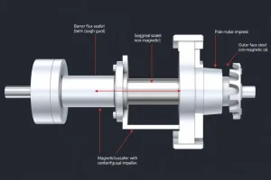
- Closed‑volute (sealed‑cavity) type: The pump housing contains a permanent liquid chamber; priming capacity is limited by that chamber volume.
- Open‑cavity (re‑circulating) type: A portion of the discharge flow is routed back to the inlet, continuously re‑pressurising the suction line. This variant offers higher priming capacity but incurs a modest efficiency penalty.
Worked Example
Example 1 – US customary units
Design data:
- Desired flow Q = 800 gpm
- Rated head H = 150 ft
- Maximum dry suction lift = 12 ft
- NPSHr (manufacturer) = 10 ft
- Atmospheric pressure = 14.7 psi (≈ 144 in H₂O)
- Vapor pressure of water at 80 °F = 0.44 psi
- Friction loss in suction pipe (50 ft of 2‑in. Schedule 40) ≈ 2 ft
Step‑by‑step:
- Convert pressures to feet of water: (frac{P_{atm}-P_{v}}{gamma}) = (frac{14.7-0.44}{0.433}) ≈ 32.8 ft.
- Add static lift (pump 12 ft below source): 12 ft.
- Subtract friction: 2 ft.
- NPSHa = 32.8 + 12 - 2 = 42.8 ft.
- Compare with NPSHr = 10 ft → NPSHa > NPSHr, so the pump will self‑prime comfortably.
Result: The pump can develop the required 150 ft head while maintaining a safe margin of 32.8 ft of NPSH.
Example 2 – SI units
Design data:
- Flow Q = 1900 L/min (≈ 31.7 L/s)
- Rated head H = 45 m
- Maximum dry suction lift = 4.5 m
- NPSHr = 3.0 m
- Atmospheric pressure = 101.3 kPa
- Vapor pressure of water at 30 °C = 4.24 kPa
- Friction loss in suction line (30 m of 50 mm DN50 steel pipe) ≈ 0.6 m
- Convert pressure difference to metres of water: (frac{p_{atm}-p_{v}}{rho g}) = (frac{101.3-4.24}{9.81times1000}) ≈ 9.9 m.
- Add static lift: 4.5 m.
- Subtract friction: 0.6 m.
- NPSHa = 9.9 + 4.5 - 0.6 = 13.8 m.
- Since 13.8 m > NPSHr (3.0 m), the pump will self‑prime with ample margin.
Result: The pump meets the required head and can be started from a dry suction condition.
Calculator
For rapid NPSH calculations, use the online tool at http://pumpcalcs.com/calculators/total-dynamic-head/.
Reference Values & Typical Ranges
- Priming capacity: 150–400 gpm (570–1500 L/min) for standard 2‑inch inlet units.
- Maximum dry suction lift: 10–25 ft (3–7.5 m) for water at 68 °F (20 °C).
- NPSHr (water): 8–12 ft (2.4–3.7 m) for 1‑to‑2‑stage designs.
- Overall efficiency at BEP: 65–78 %.
- Typical discharge pressure rating: 250–600 psi (1.7–4.1 MPa).
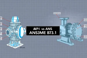
Sources: API 676, ASME B73.1, and IEC 60534‑2‑1.
Application Guidance
When evaluating a self‑priming pump for a given system, follow these steps:
- Confirm that the required suction lift does not exceed the manufacturer’s rated dry‑lift value.
- Calculate NPSHa using the method above; maintain a safety margin of at least 1.5 × NPSHr.
- Match the pump’s priming capacity to the volume of liquid that may be present in the suction line after a shutdown (e.g., pipe length × diameter × liquid fraction).
- Check that the pump’s rated flow and head intersect the system curve within the 75‑95 % efficiency band.
- Consider material compatibility (e.g., stainless steel for corrosive wastewater) and seal type (mechanical vs. gland packing) based on the fluid’s abrasiveness.
Field‑judgment adjustments such as increasing pipe diameter to reduce friction or adding a vent valve to aid air evacuation can improve priming reliability.
Common Mistakes, Limits & Safety Notes
- Neglecting vapor pressure. At elevated temperatures vapor pressure rises sharply, reducing NPSHa. Always use temperature‑corrected values.
- Mixing US and SI units. A common source of error; keep all quantities in one system until the final conversion.
- Assuming any centrifugal pump will self‑prime. Only pumps expressly designed with a sealed cavity or re‑circulation loop have the capability.
- Over‑estimating priming capacity. The sealed‑cavity volume is fixed; large suction pipe volumes may exceed it, causing failure to prime.
- Ignoring suction‑line air traps. Air pockets downstream of the pump can block priming; install vent valves or air‑release fittings.
- Operating above the rated dry‑lift. This leads to cavitation, excessive vibration, and possible seal rupture.
- Failure to protect against back‑pressure. If the discharge valve closes while the pump is primed, the sealed cavity can over‑pressurise; install a pressure relief valve.
- Inadequate grounding and electrical protection. Self‑priming pumps often run in wet environments; follow NFPA 70 and IEC 60204‑1 for safety.
FAQ
Can any centrifugal pump be used as a self‑priming pump?
No. Only pumps specifically designed with a sealed cavity or re‑circulation loop can develop the suction lift required to evacuate air. Using a standard centrifugal pump without these features will fail to prime.
What is the typical maximum suction lift for water at 68 °F?
For most self‑priming pumps, the dry suction lift limit is between 10 and 25 ft (3–7.5 m) for water at standard temperature and pressure. Exceeding this limit increases the risk of cavitation.
How does temperature affect self‑priming performance?
Higher temperatures raise the liquid’s vapor pressure, which reduces NPSHa. Designers must recalculate NPSH using the actual operating temperature to ensure a sufficient safety margin.
Do I need a foot valve when using a self‑priming pump?
A foot valve is not required for priming, but it can help retain liquid in the suction pipe after shutdown, reducing the volume the pump must evacuate on restart.
What maintenance tasks are unique to self‑priming pumps?
Inspect the sealed cavity for corrosion, verify the re‑circulation bypass valve operation, and periodically check the vent valve for blockage. Seal wear is also critical because the pump often operates with internal air‑liquid mixtures.
Can a self‑priming pump handle viscous fluids?
Viscous fluids increase friction losses and reduce priming capacity. Manufacturers provide corrected NPSHr curves for higher viscosities; if the fluid viscosity exceeds the pump’s rating, a positive‑displacement pump may be more appropriate.
Why does a self‑priming pump lose efficiency during priming?
During the initial air‑evacuation phase, a portion of the impeller’s kinetic energy is consumed in moving air rather than liquid, which lowers hydraulic efficiency until a fully liquid‑filled cavity is established.
Is it safe to operate a self‑priming pump at full discharge pressure while priming?
No. Full discharge pressure should be applied only after the pump has successfully primed. Applying high discharge pressure during priming can over‑pressurise the sealed cavity and damage seals.
Leave a Reply