
Short Answer
Two Fundamental Types: Centrifugal vs. Positive Displacement
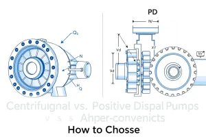
All pumps fall into two categories defined by how they move fluid:
| Characteristic | Centrifugal | Positive Displacement |
|---|---|---|
| Operating principle | Accelerates fluid radially outward with a spinning impeller | Traps a fixed volume and pushes it forward each cycle |
| Flow characteristic | Varies with head; zero at shutoff, maximum at zero head | Nearly constant regardless of head (until pressure relief opens) |
| Pressure generation | Continuous, smooth. Head and pressure rise smoothly with impeller speed. | Pulsating. Pressure rises sharply to whatever the system demands, limited only by relief valve or driver power. |
| Best for | High flow, variable head, clean fluids | High pressure, low flow, viscous fluids, metering applications |
| Typical flow range | 10 GPM to 10,000+ GPM | 0.01 GPM to 1,000 GPM (varies by type) |
| Typical pressure range | 10 psi to 300+ psi | 50 psi to 5,000+ psi (varies by type) |
| Efficiency plateau | 65–90% at BEP; drops sharply away from BEP | 85–98% across a wide flow range |
| Efficiency at low flow | Poor; severe recirculation below ~40% BEP | Excellent; nearly constant efficiency from 10% to 110% of rated flow |
| Cavitation risk | High; requires careful NPSH management | Low; high inlet pressure not needed |
| Cost (same flow/pressure) | Lower | Higher |
| Maintenance | Moderate; bearing wear, seal replacement | Moderate to high depending on type; internal clearances tighter |
| Noise | Relatively quiet | Pulsating noise characteristic of the type |
When to choose each:
- Choose centrifugal if: you need high flow, head varies with the system (piping resistance), fluid is clean or low-viscosity, and cost matters.
- Choose positive displacement if: you need constant flow regardless of head, fluid is viscous or abrasive, pressure is high, or precise metering is required.
Centrifugal Pumps: The Family Overview
How a Centrifugal Pump Works
A centrifugal pump converts mechanical energy into kinetic energy. An electric motor (or other driver) spins a shaft at a fixed speed (typically 1,200, 1,800, 2,900, or 3,600 RPM in North America). The shaft is attached to an impeller—a wheel with curved blades—that sits inside a casing (volute or diffuser).
Fluid enters at the center (eye) of the impeller and is accelerated radially outward by the rotating blades. This radial acceleration creates a pressure difference: low pressure at the center (suction inlet), high pressure at the rim (discharge). The fluid spirals outward and is collected in the casing, where the spiral shape converts the kinetic energy (velocity) into pressure energy (head).
Specific Speed: The Dimensionless Performance Number
Engineers use a parameter called specific speed (Ns) to classify centrifugal pump architectures and predict their operating characteristics:
$$N_s = \frac{N \times \sqrt{Q}}{H^{0.75}}$$
where:
- $N$ = rotational speed (RPM)
- $Q$ = flow rate (GPM)
- $H$ = head at BEP (ft)
(In SI: $N_s = \frac{N \times \sqrt{Q \text{ (m}^3\text{/h)}}}{H \text{ (m)}^{0.75}}$)
Specific speed predicts the pump’s shape and performance:
- Low Ns (500–2,000): Radial-flow impeller, steep curve, high head at low flow → end suction, vertical turbine
- Medium Ns (2,000–5,000): Mixed-flow impeller, medium head at medium flow → split case, overhung
- High Ns (5,000–10,000+): Axial-flow impeller, low head at high flow → propeller, axial-flow
Specific speed is the reason a 1,000 GPM / 100 ft pump looks completely different from a 1,000 GPM / 10 ft pump. The latter is a flat, disk-like axial design; the former is a taller, narrower radial design.
Centrifugal Architecture 1: End Suction Pumps
Description
An end suction pump (also called an “ANSI pump” in the US, referring to ANSI/ASME B73.1 standard dimensions) has:
- A single impeller on one end of the shaft.
- Suction inlet on one side of the casing (perpendicular to the discharge).
- Discharge port on top or side of the casing.
- Bearing frame that overhangs the pump casing on the discharge end.
The impeller is enclosed in a relatively small casing; the pump is compact and modular.
Applications
- Well and booster pumps: the standard in residential water service.
- HVAC hydronic circulation: small commercial heating/cooling loops.
- Low-flow, high-head applications: laboratory, process, medical (non-critical).
- Cost-sensitive applications: end suction pumps are the cheapest centrifugal option per unit displacement.
Strengths
- Low cost. The simplest centrifugal design; lowest price per GPM at moderate head.
- Easy installation. Compact footprint, bolts to a standard motor or coupling frame.
- High specific speed range. Available from very low flow / very high head to moderate flow / moderate head.
- Modular. Impellers can be trimmed (cut down in diameter) to adjust the curve.
Limitations
- Cannot be flooded. The pump must be primed (filled with liquid) before starting; it cannot handle suction lift above ~25–30 ft.
- Single impeller size. If application grows and you need 20% more head, you cannot add an impeller; you need a different pump.
- Shaft bending stress. The overhung bearing arrangement puts the impeller weight beyond the rear bearing, creating bending stress on the shaft. This limits the impeller size and speed before bearing life suffers.
- Recirculation at very low flow. Below ~40% of BEP, internal recirculation damages efficiency and can cause seal failure.
Typical Specifications
| Parameter | Range |
|---|---|
| Flow | 5–500 GPM (small to medium) |
| Head | 20–300 ft (low to high) |
| Temperature | −40°F to +250°F typical (material-dependent) |
| NPSH Required | 3–8 ft |
| Efficiency at BEP | 65–85% |
Selection Guidance
End suction pumps are the default choice for small-to-medium applications: wells, boosters, HVAC. If you need flooded suction (the water level is above the pump), upgrade to a submersible or vertical turbine. If you need very high flow and high head simultaneously, consider split case instead.
Centrifugal Architecture 2: Split Case (Double Suction) Pumps
Description
A split case pump has:
- Two impellers in series (stacked on the same shaft), or a single impeller with suction ports on both sides (double-suction impeller).
- A casing split horizontally into an upper and lower half, bolted together.
- Suction and discharge nozzles typically on the side of the lower casing.
- The pump casing sits between two bearing frames.
The split construction allows the pump to be disassembled without removing the motor or piping—this is the big maintenance advantage.
Applications
- Large commercial and industrial systems: HVAC for office buildings, shopping centers.
- Fire protection: split case pumps are the standard for fire sprinkler systems (NFPA 20 listed).
- Water utilities: municipal water distribution, water treatment plant circulation.
- High-flow cooling: power plants, data centers.
Strengths
- High flow capacity. 200–5,000 GPM easily; largest split cases exceed 10,000 GPM.
- Two impellers in series: can achieve high head (150–500 ft) without running at extreme speed.
- Serviceability. Split casing allows impeller removal and seal service without breaking discharge piping.
- Balanced design. The double-suction impeller or tandem arrangement reduces radial forces on the shaft, allowing higher speeds and longer bearing life.
- Wide efficiency range. Split case pumps often maintain >80% efficiency across 60–120% of BEP.
Limitations
- Higher cost. Roughly 2–4× the price of an equivalent end suction pump.
- Heavier and larger footprint. Not suitable for space-constrained installations.
- Requires flooded suction or careful NPSH management. The larger casing and complexity mean higher friction loss on the suction side.
- Cavitation-prone if not sized correctly. High Ns values (medium to high specific speed) means higher NPSH requirements.
Typical Specifications
| Parameter | Range |
|---|---|
| Flow | 200–5,000 GPM |
| Head | 50–500 ft (low to very high) |
| Temperature | −20°F to +200°F typical |
| NPSH Required | 6–20 ft |
| Efficiency at BEP | 80–92% |
Selection Guidance
Split case pumps are the workhorse of large commercial HVAC and industrial systems. They are overkill for small applications but provide unmatched serviceability and efficiency at medium-to-large scale. If fire protection is required, split case is often mandatory (check local codes and NFPA 20).
Centrifugal Architecture 3: Vertical Turbine Pumps
Description
A vertical turbine pump (also called a lineshaft pump or turbine pump) is a centrifugal pump designed to operate with the shaft vertical and the impeller(s) submerged in the fluid. The impeller and multiple stages (usually 1–20) are stacked on a long shaft that extends upward, with a motor mounted on top. The shaft is supported by short bearing tubes called lineshaft bearings, spaced every 5–10 feet.
Applications
- Deep wells: the most common application; wells 50–1,000 feet deep routinely use vertical turbine pumps.
- Ponds and reservoirs: pumping from lakes or large storage basins.
- Intake structures: municipal water intakes, river pumping stations.
- Flooded suction requirements: any application where the suction fluid is above the pump.
Strengths
- Flooded suction. The impeller is submerged, so NPSH is automatically satisfied. No priming required.
- Extreme suction lift capability. Can handle thousands of feet of lift (the fluid is pulling the pump down, not the pump pulling the fluid up).
- High head achievable. With 10+ stages, vertical turbine pumps easily reach 500–2,000 ft of head.
- Long bearing life. The vertical orientation distributes forces more favorably than overhung designs.
- Compact horizontal footprint. The motor sits on top; the pump occupies minimal floor space.
Limitations
- Expensive to install. The lineshaft, bearings, and motor mount are specialized, and installation requires experience.
- Lineshaft bearing maintenance. The bearings must be lubricated every 50–100 hours of operation (water-lubricated designs) or less frequently (oil-lubricated designs). Failure to lubricate leads to rapid bearing wear.
- Cavitation at the bottom stages. In very deep wells, the pressure at the bottom impellers can drop below vapor pressure, causing cavitation at the lowermost stage. Design must account for this.
- Repair requires pulling the entire assembly. If an impeller fails, the lineshaft and motor must be lifted out of the well—expensive and time-consuming.
Typical Specifications
| Parameter | Range |
|---|---|
| Flow | 50–2,000 GPM |
| Head | 50–2,000+ ft (can be extreme) |
| Number of stages | 1–20 (or more) |
| Temperature | −20°F to +140°F typical |
| NPSH Required | Minimal (impeller submerged) |
| Efficiency at BEP | 75–88% |
Selection Guidance
If you are pumping from a deep well or reservoir, vertical turbine is the standard solution. Submersible pumps are an alternative for some applications; vertical turbine is preferred for high flow or when the well is of extreme depth. Always verify lineshaft bearing type (water-lubricated vs. oil-lubricated) and maintenance requirements before procurement.
Centrifugal Architecture 4: Multistage Pumps
Description
A multistage pump stacks multiple impellers in series on a single shaft, each with its own diffuser or return channel. The discharge from one impeller becomes the inlet to the next. The heads add; if each stage is rated at 100 ft, a 3-stage pump produces 300 ft.
Multistage pumps are commonly:
- Submersible: the entire assembly (motor, impellers, diffusers) is lowered into the well or basin.
- Horizontal split case: two or more impellers inside a horizontally split casing.
- Centrifugal (in-line): impellers stacked inside a long cylindrical casing, with suction and discharge on opposite ends of the same axis (common in HVAC).
Applications
- Deep wells (via submersible multistage): standard for domestic wells 100–500 ft deep.
- High-head, moderate-flow requirements: booster stations, mountain communities.
- HVAC hydronic: in-line multistage pumps for large buildings.
- Firefighting and pressure boosting: very high head required at moderate flow.
Strengths
- Extreme head from a single pump. Achieves 500–2,000+ ft without exotic speeds.
- Modular design. Impellers and diffusers are repeated stages; manufacturing is straightforward.
- Reasonable efficiency at high head. A 10-stage pump running at 1,800 RPM reaches high head without excessive speed and the corresponding cavitation risk.
Limitations
- Cost: Each additional stage adds material, complexity, and cost.
- Length and weight: Many stages in a single pump result in a long, heavy assembly. For a submersible, this is manageable; for horizontal centrifugal, it requires a larger bearing frame.
- Cavitation risk at multiple points: Each stage has its own inlet, and if NPSH is marginal, cavitation can occur at any stage. The lowest stage is at highest risk.
Typical Specifications (Submersible Multistage Example)
| Parameter | Range |
|---|---|
| Flow | 10–500 GPM (most common: 50–200 GPM) |
| Head | 200–2,000 ft (or higher) |
| Number of stages | 3–20 |
| Temperature | −20°F to +140°F typical |
| Power | 0.5–15 HP |
| Efficiency at BEP | 70–88% |
Centrifugal Architecture 5: Submersible Pumps
Description
A submersible pump is a complete pumping unit (multistage centrifugal pump + electric motor) sealed in a single steel cylinder, designed to operate fully submerged in the fluid being pumped. The motor and pump share the same oil-filled cavity, and cooling comes from the fluid flowing through the motor winding cavity. The entire assembly is lowered into the well or basin on a drop pipe (or riser), and power is delivered through a weatherproof cable.
Applications
- Domestic and agricultural wells: the most common pump type for residential water systems.
- Irrigation wells: high-volume irrigation from boreholes.
- Sewage lift stations: submersible sewage (chopper) pumps handle solids.
- Aquaculture and pond pumping: fish hatcheries, ornamental ponds.
- Dewatering: temporary water removal during construction or maintenance.
Strengths
- No priming required. The pump is submerged; suction is automatic.
- Compact installation. The entire unit fits in the borehole; no surface footprint except the discharge.
- Low maintenance. No lineshaft bearings to lubricate; the motor is sealed and cooled by the fluid.
- Quiet operation. The fluid surrounding the motor dampens noise.
- High reliability. Submersible pumps typically operate unattended for years.
Limitations
- Difficult to service. Repairs require pulling the entire pump out of the well—expensive and time-consuming if the well is very deep.
- Motor cooling is flow-dependent. If the pump is running against a closed valve (dead-head), the motor can overheat because there is no flow to cool the winding.
- Cable and seals are failure points. The power cable must be rated for outdoor/wet conditions; the seal where the cable enters the pump is a common failure site. Water ingress into the motor oil means motor failure within weeks.
- Pressure rating of the borehole. Submersible motors are rated for a maximum water pressure (often 300 psi); extremely deep wells can exceed this rating. Vertical turbines handle extreme depth better.
Typical Specifications (Domestic Submersible)
| Parameter | Range |
|---|---|
| Flow | 5–200 GPM typical |
| Head | 100–500 ft typical |
| Horsepower | 0.5–5 HP most common |
| Motor type | 1-phase (residential) or 3-phase (commercial) |
| Cable length | Custom; 50–500+ feet available |
| Pressure rating | 100–300 psi typical |
| Efficiency at BEP | 65–82% |
Selection Guidance
For any new well, submersible is the default choice. It is cost-effective, reliable, and requires minimal site work. The main trade-off is that repairs are expensive (pulling time + service call). For very deep wells (>500 ft) or very high flow (>500 GPM), compare against vertical turbine for cost and serviceability.
Centrifugal Architecture 6: Self-Priming Pumps
Description
A self-priming pump is a centrifugal pump modified to automatically refill its casing with liquid on startup, even if the suction line is not flooded. A large reservoir (or priming chamber) sits on top of the casing; when the pump starts, it pulls air and liquid from the suction line into this chamber. Inside the chamber, a specially designed rotor separates the air (expelled to atmosphere through a vent) from the liquid (sent back to the suction line via an internal bypass). This cycle repeats until the casing fills with liquid and the pump begins normal operation.
Applications
- Sewage and wastewater transfer: non-flooded suction, contaminated fluid.
- Slurry and solids-laden applications: dredging, mining, agricultural waste.
- Emergency and temporary pumping: disaster relief, construction dewatering.
- Short suction lift (up to ~20 ft): faster priming than manual priming.
Strengths
- No manual priming. Start the pump; it primes itself automatically within 30–60 seconds.
- Handles solids and air. Can tolerate some entrained solids and air pockets in the suction line without losing prime.
- Relatively compact. Smaller than a parallel-plate self-priming pump but more robust than standard centrifugal.
Limitations
- Lower efficiency. The priming chamber and internal bypass paths create turbulence and head loss. Efficiency is typically 10–20% lower than a standard centrifugal at the same duty.
- More maintenance. The priming chamber has more surfaces to foul; debris must be cleaned out periodically.
- Cannot exceed ~25 ft suction lift. The priming method has a limit; extreme suction lift requires a submersible or flooded suction.
- Higher cost. Self-priming versions cost 30–50% more than equivalent standard centrifugal pumps.
Typical Applications and Specifications
| Application | Flow | Head | NPSH Required |
|---|---|---|---|
| Sewage transfer | 100–2,000 GPM | 30–100 ft | None (non-flooded) |
| Dredging | 500–5,000 GPM | 20–80 ft | None (often suction lift) |
| Slurry | 100–1,000 GPM | 20–150 ft | Moderate |
Specialized Centrifugal Variants: Magnetic Drive and Sealless Pumps
Magnetic Drive Pumps
A magnetic drive pump uses magnetic coupling between the motor shaft and the pump impeller, eliminating the mechanical shaft seal entirely. A magnet attached to the motor shaft spins an inner magnet on the pump side; the impeller is attached to the inner magnet. Between them is a thin, sealed non-magnetic barrier. The magnetic force transmits torque through the barrier without a physical connection.
Advantages:
- No shaft seal: eliminates seal leakage and maintenance.
- Containment: suitable for toxic, radioactive, or hazardous liquids (chemistry labs, nuclear facilities, pharmaceutical).
- Quiet operation: the magnetic coupling has no friction or vibration.
Disadvantages:
- High cost: magnetic couplings are expensive; prices are 2–4× standard pumps.
- Slip limit: if the load exceeds the magnetic torque, the coupling slips and the pump stops. No relief mechanism; loss of magnetic coupling means no flow, not pressure limitation.
- Lower efficiency: the magnetic gap and barrier introduce additional loss.
- Lower maximum pressure: typically limited to 100–200 psi due to coupling slip characteristics.
- Sizing must be exact: overspeed or overload causes the coupling to slip. No headroom for design changes.
Sealless Pumps (Canned Motor Design)
A canned motor pump has the motor winding completely sealed inside a thin stainless steel can filled with the process fluid itself. The rotating shaft passes through the can via a magnetic bearing (no seal). The fluid being pumped cools and lubricates the motor.
Advantages:
- Zero leakage: ideal for toxic/hazardous applications.
- Compact: the motor is small and integrated with the pump.
Disadvantages:
- Very high cost: premium application-specific pricing.
- Thermal management critical: if flow stops, the motor overheats. Requires flow-sensing shutdown or cooling jacket.
- Pressure rating is low: canned motors rarely exceed 150 psi.
- Repairs require specialized technicians: not field-serviceable.
When to use: Magnetic drive and canned motor pumps are justified only when the application involves hazardous or toxic fluids where seal leakage is unacceptable. For standard industrial applications, the cost is prohibitive.
Positive Displacement Pumps: The Family Overview
Operating Principle
A positive displacement pump traps a fixed volume of fluid and forces it forward on each stroke or revolution. Unlike centrifugal pumps, which vary their flow with system resistance, PD pumps deliver nearly constant flow regardless of the head—up to the point where the relief valve opens.
Flow is determined by:
$$Q = \frac{D \times N \times \eta_v}{1000} \text{ (L/min)}$$
where:
- $D$ = displacement (cc/rev or in³/rev)
- $N$ = shaft speed (RPM)
- $\eta_v$ = volumetric efficiency (typically 0.90–0.98)
If you need 50 GPM at 1,500 RPM, you calculate the displacement needed and select a pump with that displacement. The flow will be nearly 50 GPM regardless of whether the discharge head is 50 psi or 500 psi (until relief opens).
Why Positive Displacement Pumps?
- Precise metering. Flow rate is independent of head, so dosing and transfer applications are exact.
- High-pressure capability. No cavitation risk; can operate at 2,000 psi or higher.
- High efficiency at low flow. Efficient even at 10% of rated flow, unlike centrifugal.
- Viscous fluid handling. Can pump oils, resins, slurries without significant de-rating.
- Low flow / high pressure niche. Pump 0.1 GPM at 1,000 psi; centrifugal cannot do this.
Trade-offs
- Higher cost per GPM than centrifugal at the same flow.
- Pulsating flow and noise: internal cam/gear surfaces engage and disengage repeatedly, creating noise and flow ripple.
- Higher internal leakage at high viscosity or age: seals wear, slippage increases, efficiency drops.
- Sensitivity to contamination: tight internal clearances mean particles jam the pump. Excellent filtration is mandatory.
PD Architecture 1: Gear Pumps
External Gear Pumps
An external gear pump consists of two gears (driver and idler) meshing inside a close-fitting casing. As the gears rotate, they separate on the inlet side (creating low pressure and drawing fluid in) and compress on the discharge side (pushing fluid out). Fluid trapped between a gear tooth and the casing is pushed to the discharge.
Specifications:
- Flow range: 1–500 GPM
- Pressure: up to 3,000 psi
- Efficiency: 85–95%
- Cost: moderate (lowest-cost PD pump per GPM)
Applications:
- Hydraulic power units: construction equipment, industrial machinery.
- Oil transfer: automotive, petroleum.
- Fuel pumps: light-duty fuel supply for small engines.
Advantages: Simple, robust, inexpensive, handles some solids, high pressure.
Disadvantages: Noisy, pulsating flow, sensitive to viscosity changes, limited speed (typically <2,000 RPM).
Internal Gear Pumps
An internal gear pump has a larger internally-toothed ring gear and a smaller external pinion gear inside it. The pinion rotates inside the ring, with a crescent-shaped seal between them. Flow increases as the gap opens on the inlet side and decreases as it closes on the discharge side.
Advantages over external gears: Smoother flow (single point of engagement), quieter, smaller casing.
Disadvantages: More complex to manufacture, slightly lower volumetric efficiency.
PD Architecture 2: Diaphragm Pumps
A diaphragm pump uses a flexible diaphragm (rubber or plastic membrane) that flexes in and out, alternately drawing fluid into and pushing it out of a chamber. Two check valves (ball or flapper) prevent backflow. Diaphragm pumps can be:
- Mechanical: the diaphragm is driven by a mechanical linkage or cam.
- Pneumatic: air pressure flexes the diaphragm (air-operated double diaphragm or AODD pump).
Pneumatic Diaphragm Pumps (AODD)
Air enters one side of a double diaphragm, pushing it inward. As it does, a check valve closes on the exhaust side and opens on the draw side. The displaced air exits, and the diaphragm springs back, drawing fresh fluid. The cycle repeats at the other diaphragm (hence “double”).
Advantages:
- Intrinsically safe: no electrical components; suitable for hazardous atmospheres.
- Excellent for pulsed/intermittent service: can start/stop thousands of times.
- Handles solids and abrasive fluids: large internal clearances; balls in check valves handle grit.
- Low shear: gentle on fragile solids, emulsions, or gases dissolved in the liquid.
- Self-priming: works on suction lift up to ~25 ft without external priming.
Disadvantages:
- Low pressure: typically 100–150 psi; rarely exceeds 200 psi.
- Low efficiency: 30–50% (air pressure input to useful hydraulic output); still economical if air compressor is already on site.
- Noise: pulsating and venting air is loud.
- Flow pulsation: unsuitable for applications requiring smooth flow.
Applications:
- Paint and coatings transfer: AODD pumps are the standard in paint shops, factories.
- Wastewater and sludge: handles grit and fibrous solids.
- Petroleum tank transfer: intrinsically safe for flammable vapors.
- Slurry and dredging: handles sand and debris.
Mechanical Diaphragm Pumps
A motor drives a crankshaft, which pushes a connecting rod that flexes the diaphragm. Common in:
- Metering and dosing: small mechanical diaphragm pumps for chemical addition (water treatment, laboratory).
- Household well pump boosters: occasionally.
Less common than AODD but useful for precise, continuous low-flow metering.
PD Architecture 3: Peristaltic Pumps
A peristaltic pump pumps fluid through a flexible tube or hose using rotating rollers or paddles that compress the tube in sequence, creating a wave motion that pushes fluid forward. Imagine a straw with fingers squeezing progressively along its length.
Advantages:
- No contact with the fluid: the fluid touches only the tubing; the pump internals never see the fluid. Ideal for hazardous, sterile, or shear-sensitive liquids.
- Self-priming: works against suction lift.
- Reversible: can pump backward by reversing rotation.
- Gentle on solids: no impeller blades to shred particles; handles slurries and suspensions well.
Disadvantages:
- Tube wear: the tubing is squeezed repeatedly and must be replaced every 1–3 years depending on duty.
- Low pressure: typically 20–60 psi.
- Low to moderate efficiency: 60–80%.
- Cost: high per GPM; suitable only for specialized applications where benefits justify cost.
Applications:
- Laboratory and pharmaceutical: sterile fluid transfer, metering reagents.
- Medical: IV infusions, dialysis.
- Food and beverage: juice, sauce, honey transfer without shear.
- Hazardous fluid transfer: acid, caustic, radioactive (containment via tubing).
PD Architecture 4: Progressive Cavity (Screw) Pumps
A progressive cavity pump (also called a screw pump or Moineau pump) consists of a rotating rotor (single-helix screw) inside a stationary stator (double-helix helical cavity). As the rotor turns, it creates expanding and contracting chambers along its length, progressively moving fluid from inlet to discharge.
Advantages:
- Excellent viscosity tolerance: works smoothly with heavy oils, resins, polymers with minimal de-rating.
- Smooth, pulsation-free flow: ideal for applications requiring steady discharge.
- High suction lift: can lift 25–30 ft without priming.
- Solids tolerance: can handle fiber and light slurry if designed for it.
- Reasonably high efficiency: 75–90% across a wide flow range.
Disadvantages:
- High cost: complex manufacturing; premium pricing.
- Stator wear: the stator is elastomeric and wears over time; replacement is expensive.
- Speed limitation: typically 400–1,200 RPM to avoid erosion and stator damage.
- Sensitive to sand and hard particles: unlike AODD, cannot tolerate grit.
Specifications:
- Flow range: 10–2,000 GPM
- Pressure: 100–1,000 psi typical
- Efficiency: 75–90%
Applications:
- Crude oil transfer: primary application; handles hot, viscous crude.
- Polymer and resin transfer: food thickeners, adhesives.
- Sludge and biosolids: wastewater treatment.
- Cosmetics and personal care: creams, gels, shampoos.
<a name=”piston”></a>
PD Architecture 5: Piston Pumps
A piston pump uses a swashplate mechanism to convert rotational motion into reciprocating piston motion. A rotating barrel contains multiple pistons; as the barrel turns, a fixed angled plate (swashplate) pushes the pistons in and out. Each piston motion draws fluid in on one side and expels on the other. Check valves direct flow to discharge.
Types:
- Axial piston: pistons arranged parallel to the drive shaft; the most common design.
- Radial piston: pistons arranged perpendicular to the shaft; for very high pressure.
Advantages:
- Very high pressure: 3,000–5,000 psi common; up to 10,000 psi possible.
- High efficiency: 85–98% depending on load and speed.
- Compact: achieves high flow and pressure in a small package.
- Variable displacement: swashplate angle can be modulated to vary flow without changing speed.
Disadvantages:
- Very high cost: piston pumps are precision instruments; 5–10× the price of equivalent gear pumps.
- Sensitivity to contamination: tight clearances; excellent filtration mandatory (3–5 micron).
- Complexity: requires skilled technicians for service.
- Speed range: narrow; operating far from design speed reduces efficiency and reliability.
Applications:
- Mobile hydraulics: excavators, loaders, bulldozers.
- Industrial hydraulic systems: presses, injection molding.
- Marine: ship steering, winches.
- Aerospace: actuation systems.
PD Architecture 6: Vane and Lobe Pumps
Vane Pumps
A vane pump has a rotor with slots that house sliding vanes (flat rectangular plates). As the rotor turns inside an eccentric stator bore, the vanes slide in and out of the rotor slots, creating expanding pockets on the inlet side and contracting pockets on the discharge side.
Advantages: Compact, smooth flow, moderate efficiency (70–85%).
Disadvantages: Limited pressure (typically <200 psi), vane wear is continuous, sensitive to fluid viscosity.
Applications: Low-pressure hydraulics, power steering (legacy applications).
Lobe Pumps (Rotary Lobe)
A lobe pump (or blower when used for gas) has two rotating lobes (shaped like a figure-8 or teardrops) that mesh but do not touch. As they rotate, they create expanding chambers on the inlet side and compressing chambers on the discharge. Fluid is trapped in the expanding lobes and pushed to discharge as they rotate.
Advantages: Low shear, handles solids well, self-priming, smooth operation for a PD pump.
Disadvantages: Pulsating (higher pulse frequency than gear pumps), moderate efficiency (65–80%), lower pressure than gear or piston.
Applications: Wastewater transfer (lobe pumps are common in sewage systems), food and beverage, pharmaceutical.
Pump Selection Decision Framework
Choosing the right pump requires answering a sequence of questions:
Step 1: Determine the Application’s Duty Requirements
| Requirement | Definition | Examples |
|---|---|---|
| Flow rate | Volume per unit time needed | “Must deliver 500 GPM” |
| Head / Pressure | Pressure required to overcome system resistance | “50 ft TDH” or “100 psi” |
| Fluid properties | Viscosity, SG, solids content, temperature | “Viscous oil at 150°F” |
| Duty cycle | Continuous or intermittent? | “24/7 operation” or “1 hr/day” |
| Environment | Location, temperature, atmosphere | “Outdoor, −20°F to +110°F” |
| Cost constraint | Budget, payback period? | “Under $5,000 capital” |
Step 2: Choose Between Centrifugal and Positive Displacement
Choose centrifugal if:
- Flow > 100 GPM and head < 200 ft
- Fluid is clean or non-viscous
- Operation is continuous
- Head varies significantly with flow (demand-driven)
- Cost is primary concern
Choose positive displacement if:
- Precise metering or constant flow is required
- Pressure > 200 psi
- Fluid is viscous (> 100 cSt)
- Suction conditions are extreme (lift > 25 ft)
- Efficiency at low or zero flow matters
Step 3: Select the Architecture
For centrifugal, choose:
| Your requirement | Choose |
|---|---|
| Small flow (< 100 GPM), any head, cost-sensitive | End suction |
| Large flow (> 500 GPM), moderate head, industrial | Split case |
| Suction lift > 25 ft or flooded suction required | Submersible or Vertical turbine |
| Very high head (> 500 ft) | Multistage (submersible or horizontal) |
| Non-flooded suction with solids | Self-priming |
| Toxic fluid containment mandatory | Magnetic drive or Canned motor |
For positive displacement, choose:
| Your requirement | Choose |
|---|---|
| Moderate flow, moderate pressure, high viscosity | Gear pump |
| Must handle solids or be in hazardous area | Pneumatic diaphragm (AODD) |
| Sterile / no contamination of fluid | Peristaltic |
| Viscous, continuous (crude, resin, sludge) | Progressive cavity |
| Very high pressure (>1,000 psi) | Piston |
| Wastewater or low-pressure high-flow | Lobe |
Step 4: Confirm Sizing and Verify NPSH (Centrifugal) or Pressure Relief (PD)
For centrifugal: Calculate total dynamic head and ensure the pump curve’s maximum head ≥ your TDH at your required flow. Verify NPSH available ≥ NPSH required by the pump.
For positive displacement: Confirm the pump’s displacement and speed give you the required flow. Verify the relief valve is set appropriately.
Pump Materials of Construction
The fluid being pumped and the operating environment determine the materials:
Common Pump Casing Materials
| Material | Typical use | Pros | Cons |
|---|---|---|---|
| Cast iron | General-purpose water, moderate corrosion | Cheap, robust, works with most fluids | Rusts if not painted/lined, brittle at low temps |
| Ductile iron | Higher strength required; hot water | More impact-resistant than cast iron | Slightly more expensive |
| Stainless steel (304 or 316) | Corrosive fluids, hygienic applications | Excellent corrosion resistance; food-safe | High cost; galling risk without proper lubrication |
| Bronze | Seawater, caustic environments | Outstanding corrosion resistance | Very expensive; limited size availability |
| Thermoplastic (PVC, polypropylene) | Acids, bases, chemical transfer | Chemical-resistant, low cost | Pressure-limited (~150 psi); temperature-limited |
Impeller and Shaft Materials
- Carbon steel: general purpose, economical.
- Stainless steel: corrosion-prone fluids.
- Bronze/brass: seawater, caustic.
- Ni-resist or duplex stainless: severe corrosion (acids, mines).
Related Calculations and Further Reading
Recommended Calculators on PumpCalcs.com
- Pump Selection Screener — A decision tree to help narrow the pump type based on flow, head, viscosity, and application.
- Positive Displacement Pump Displacement & Flow — Calculate displacement or flow for a PD pump.
- Pump Power Calculator — Estimate the motor required for any pump at your duty point.
- Impeller Trim Calculator — Estimate the effect of trimming a centrifugal pump impeller.
- System Curve & Duty Point — Plot pump curves and system curves to find the duty point.
Engineering Standards and References
- ANSI/HI 14.1–14.2: Centrifugal Pump Nomenclature, Definitions, Applications, and Operation. Defines pump types, terminology, and performance criteria.
- API 610 (11th edition): Centrifugal Pumps for Petroleum, Petrochemical, and Natural Gas Industries. Specification for severe-duty applications.
- ASME/ANSI B73.1: Specifications for End Suction Centrifugal Pumps (Horizontal and Vertical).
- NFPA 20: Installation of Stationary Fire Pumps for Fire Protection. Governs fire pump selection and testing.
- ISO 5199: Centrifugal Pumps—Code of Practice for Installation, Operation, and Maintenance.
- ISO 4415: Hydraulic fluid power—General rules and safety.
Recommended Books
- Menon, E. Shashi: Working Guide to Pump and Pumping Stations. Elsevier, 2009. Comprehensive, practical, with case studies.
- Cameron Hydraulic Data. Flowserve. The reference text for hydraulic calculations, material data, and pump performance.
Verification and Disclaimer
Content verification: All pump type descriptions and performance data have been cross-checked against ANSI/HI standards, API 610, and manufacturer technical data. Specific speed formulas are from Hydraulic Institute definitions.
Recommended use: This article provides an overview of pump types and selection criteria for educational and preliminary design purposes. Final pump selection should be verified with manufacturer performance curves, technical data, and consultation with the pump supplier or a licensed professional engineer. Do not rely solely on this guide for critical applications.
Last updated: July 2026 | Reviewed by: [PE Reviewer Name, [State] PE License [Number]] | Reading time: ~22 minutes
FAQ
What is the main difference between centrifugal and positive displacement pumps?
Centrifugal pumps create flow by adding kinetic energy to the fluid, while positive displacement pumps move a fixed volume of fluid per rotation or stroke, making flow largely independent of system pressure.
When should I choose a positive displacement pump over a centrifugal pump?
Use a PD pump for high‑viscosity liquids, precise metering, high‑pressure service, or when a constant flow is required despite pressure variations.
How does NPSH affect pump performance?
Insufficient NPSH leads to cavitation, which can erode impellers and reduce efficiency. The available NPSH must exceed the required NPSH by a safety margin (typically 2‑3 ft).
Can I improve the efficiency of an existing centrifugal pump?
Yes. Options include impeller trimming, reducing clearance, installing a VFD, and optimizing suction piping to reduce losses.
What maintenance practices extend the life of positive displacement pumps?
Regular lubrication, seal inspection, monitoring wear rings, vibration analysis, and keeping the pump free of solids are essential for longevity.
Leave a Reply