
Short Answer
Key Formula / Key Facts Box
| Symbol | Meaning | US Unit | SI Unit | Plain‑English Restatement |
|---|---|---|---|---|
| Q | Volumetric flow rate | gpm (gal/min) | m³/h | How much liquid passes through the pump per unit time. |
| H | Total dynamic head | ft | m | The equivalent height the pump must lift the fluid, including losses. |
| η | Overall efficiency (hydraulic × motor) | decimal (‑) | decimal (‑) | Ratio of useful power out to power supplied. |
| ρ | Fluid density | lb/ft³ | kg/m³ | Mass per unit volume of the pumped fluid. |
| g | Acceleration of gravity | 32.174 ft/s² | 9.80665 m/s² | Force that gives weight to a mass. |
| NPSH_R | Required net positive suction head | ft | m | Minimum suction head needed to keep the pump from cavitating. |
Governing hydraulic‑power equation (both US‑customary and SI forms):
[ P_{hyd}=frac{ρ,g,Q,H}{η} ]
When expressed in horsepower (hp) for water at 4 °C, the constant ρ·g/550 simplifies to ≈0.00264, yielding [P_{hyd}(hp)=frac{Q(gpm),H(ft)}{3960,η}]. In SI units, [P_{hyd}(kW)=frac{ρ,g,Q(m³/h),H(m)}{3600,η}] which reduces to [P_{hyd}(kW)=frac{Q,H}{367,η}] for water.
Overview — What It Is and Why It Matters
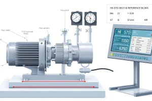
A pump nameplate is a permanent metal tag welded or bolted to the pump housing. It lists the manufacturer‑approved design point and operating limits: flow (Q), head (H), shaft power (P), rotational speed (N), overall efficiency (η), required net positive suction head (NPSH_R), material construction, temperature rating, and applicable standards (ANSI, ISO, IEC). The accompanying datasheet expands on the nameplate, providing performance curves, dimensional drawings, vibration limits, and compliance declarations.
Accurate interpretation of these markings is critical for three reasons: (1) selecting a pump that can meet the system’s flow‑head requirement without excessive energy use; (2) ensuring the motor and suction conditions are sized to avoid cavitation, overheating, or premature bearing wear; and (3) documenting the correct operating point for maintenance, troubleshooting, and regulatory reporting. Misreading a single field can cascade into undersized equipment, safety hazards, and costly downtime.
The Method — Derivation and Variants
The core relationship derives from the definition of hydraulic power as the product of pressure and volumetric flow. Pressure expressed as a head (H) multiplied by fluid weight (ρ·g) gives the force per unit area, and multiplying by flow (Q) yields power:
P_{hyd}=ρ,g,Q,H
Because a pump is not perfectly efficient, the shaft power required from the motor must be divided by the overall efficiency η:
P_{shaft}=frac{P_{hyd}}{η}
Finally, the motor’s electrical rating (P_{motor}) is obtained by dividing shaft power by the motor’s own efficiency (typically 0.90–0.95 for standard induction motors).
US‑customary form (ft, gpm, hp):
P_{hyd}(hp)=frac{Q(gpm),H(ft),ρ(lb/ft³),g(ft/s²)}{550,η}
For water at 4 °C, ρ·g/550 ≈ 0.00264, which simplifies to the widely used water‑only equation:
P_{hyd}(hp)≈frac{Q(gpm),H(ft)}{3960,η}
SI form (m³/h, m, kW):
P_{hyd}(kW)=frac{ρ,g,Q(m³/h),H(m)}{3600,η}
With ρ≈1000 kg/m³ and g≈9.81 m/s², the constant becomes 0.00981, giving the convenient water‑only version:
P_{hyd}(kW)≈frac{Q(m³/h),H(m)}{367,η}
These variants allow engineers to back‑calculate any missing parameter directly from the nameplate data, provided the fluid properties and efficiency are known.
Worked Example
Example 1 – US Units
A centrifugal pump for water (ρ≈62.4 lb/ft³) is marked:
- Flow Q = 2,500 gpm
- Head H = 150 ft
- Efficiency η = 0.78 (78 %)
- Motor rating = 150 hp
Calculate hydraulic power and verify motor adequacy.
- Apply the water‑only equation: (P_{hyd}=frac{Q,H}{3960,η}).
- (P_{hyd}=frac{2,500times150}{3,960times0.78}=frac{375,000}{3,088.8}approx121.5,hp).
- Assume motor efficiency 0.92: (P_{shaft}=frac{121.5}{0.92}approx132,hp).
- The nameplate motor rating (150 hp) exceeds the required shaft power by about 12 %, satisfying the typical 10–20 % safety margin.
Example 2 – SI Units
Convert the same pump data to SI (water at 20 °C, ρ≈998 kg/m³):
- Flow Q = 2,500 gpm = 9.46 m³/min = 567.6 m³/h
- Head H = 150 ft = 45.72 m
- Efficiency η = 0.78
- Motor rating = 112 kW (≈150 hp)
Calculate hydraulic power using the full SI equation:
- Convert flow to m³/s: (Q=567.6,text{m³/h}=0.1577,text{m³/s}).
- (P_{hyd}=frac{ρ,g,Q,H}{η}=frac{998times9.81times0.1577times45.72}{0.78}approx90.7,kW).
- Assuming motor efficiency 0.92, (P_{shaft}=frac{90.7}{0.92}approx98.6,kW).
- The supplied motor (112 kW) provides a 14 % margin, confirming adequacy.
This side‑by‑side demonstration highlights the importance of consistent unit conversion and the utility of the governing equations.
Calculator
For rapid verification, use an online pump‑power calculator such as the Pump Power & Head Calculator.
Reference Values & Typical Ranges
- Flow rates: 10 gpm (0.04 m³/h) to 100,000 gpm (378 m³/h) for most industrial centrifugal pumps.
- Total dynamic head: 10 ft (3 m) to 2,000 ft (610 m) depending on application.
- Motor power: 0.5 hp (0.37 kW) to 5,000 hp (3,730 kW).
- Overall efficiency at Best Efficiency Point (BEP): 45 %–85 %; premium magnetic‑drive designs can exceed 90 %.
- Required NPSH (NPSH_R): 2 ft (0.6 m) to 30 ft (9 m) for typical water‑based pumps.
- Operating temperature (common alloys): –20 °F (‑29 °C) to 300 °F (149 °C).
- Design speed (N): 600 rpm to 3,600 rpm for standard end‑suction centrifugal pumps.
Application Guidance
- Read the nameplate flow (Q_np) and head (H_np) as the intended design point.
- Obtain the pump’s performance curve from the datasheet and overlay the system curve (head loss vs. flow). The intersection is the actual operating point.
- Verify that the operating point lies within ±10 % of the BEP; this maximizes efficiency and prolongs bearing life.
- Compare the system’s available NPSH (NPSH_A) with the nameplate NPSH_R. Maintain at least a 0.5 m (1 ft) margin to guard against suction cavitation.
- Calculate required shaft power using the equations above and select a motor whose rated power exceeds the result by 10 %–20 % to accommodate start‑up currents and future load growth.
- If variable flow is required, consider a pump with a broad efficiency plateau or a variable‑frequency drive (VFD) capable of maintaining NPSH_A across the range.
- Document the verified operating point in the maintenance log; periodic re‑validation prevents drift caused by wear or process changes.
Common Mistakes, Limits & Safety Notes
- Unit mix‑up: Substituting gpm for m³/h or ft for m introduces 3–4× errors in power calculations.
- Ignoring NPSH_R: Selecting a pump whose required NPSH exceeds the system’s available NPSH leads to cavitation, vibration, and seal failure.
- Assuming 100 % efficiency: Over‑optimistic power estimates will undersize the motor and increase energy costs.
- Using nameplate flow at a different speed: Many nameplates are rated at a single RPM; if the pump operates at another speed, scale flow (Q ∝ N) and head (H ∝ N²) accordingly.
- Overlooking temperature effects: Fluid viscosity rises with lower temperature, reducing efficiency and increasing NPSH_R; exceedance of material temperature limits can cause corrosion or cracking.
- Skipping motor safety margin: Motors experience high in‑rush currents; a 10 %–20 % power margin prevents overload trips and prolongs motor life.
- Operating near shut‑off head: Close to zero flow, radial loads increase dramatically, accelerating bearing wear and impeller imbalance.
- Neglecting shaft alignment: Misalignment between pump and motor introduces axial loads, reduces efficiency, and accelerates bearing wear.
FAQ
What information is typically found on a pump nameplate?
A nameplate usually lists the model number, design flow (Q), total dynamic head (H), shaft power (P), rotational speed (N), overall efficiency (η), required NPSH (NPSH_R), material construction, temperature limits, and applicable standards.
How do I convert the flow rate from gpm to m³/h?
Multiply the flow in gallons per minute by 0.003785 m³/gal and then by 60 min/h. For example, 2,500 gpm × 0.003785 × 60 ≈ 567.6 m³/h.
Why is NPSH_R important and how is it used?
NPSH_R is the minimum suction head required to keep the pump from cavitating. Compare it with the system’s available NPSH (NPSH_A); NPSH_A should exceed NPSH_R by at least 0.5 m (1 ft) to ensure safe operation.
Can I use a pump at a speed different from the nameplate rating?
Yes, but you must scale flow and head: flow varies linearly with speed (Q ∝ N) and head varies with the square of speed (H ∝ N²). Re‑calculate the operating point and verify efficiency and NPSH limits.
What safety margin should I apply when selecting a motor?
Industry practice is to choose a motor whose rated power is 10 %–20 % higher than the calculated shaft power. This accounts for start‑up currents, future load increases, and minor efficiency variations.
How do temperature and fluid viscosity affect pump performance?
Higher viscosity (lower temperature) increases friction losses, raises NPSH_R, and reduces efficiency. Verify that the pump’s temperature rating and the fluid’s viscosity at operating temperature are within the manufacturer’s limits.
What is the best way to verify that a pump meets the system curve?
Plot the system head‑loss curve (calculated from pipe friction, fittings, and static lifts) and overlay the pump’s performance curve from the datasheet. The intersection gives the actual operating point; it should lie near the BEP for optimal efficiency.
Is it acceptable to operate a pump at its shut‑off head?
Operating at shut‑off (zero flow) creates excessive radial loading and can cause premature bearing wear and seal damage. It is generally avoided unless the pump is designed for intermittent shut‑off service.
Leave a Reply