
Short Answer
Key Formula / Key Facts Box
| Pump Type | Typical Flow (US gpm / SI m³/h) | Typical Head (ft / m) | Best‑efficiency % | Max NPSH (ft / m) | Common Industries |
|---|---|---|---|---|---|
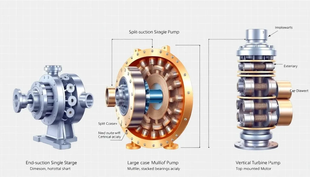
| End‑suction (single‑stage) | 10–5,000 / 0.04–19 | 30–250 / 9–76 | 65–80 | 5–25 / 1.5–7.6 | Water‑treatment, HVAC, irrigation |
| Split‑case (multi‑stage) | 500–30,000 / 2–114 | 200–1,500 / 61–457 | 70–85 | 15–45 / 4.5–13.7 | Power‑plant cooling, petrochemical, fire‑suppression |
| Vertical turbine (multistage) | 200–25,000 / 0.75–95 | 300–2,500 / 91–762 | 72–88 | 20–60 / 6–18 | Municipal water, oil‑field, large‑scale cooling |
Overview — What It Is and Why It Matters
End‑suction, split‑case, and vertical turbine pumps are three of the most widely used centrifugal pump families in the process‑industry spectrum. All three convert kinetic energy from a rotating impeller into pressure, but they differ in impeller mounting, flow‑path geometry, and the way the shaft is supported. Those differences drive distinct performance envelopes, installation footprints, and maintenance regimes. Selecting the wrong type can lead to premature cavitation, excessive vibration, or a system that simply cannot meet the required flow‑head combination.
The Method — Derivation and Variants
The fundamental head‑generation equation for any centrifugal pump is derived from the Euler turbomachinery equation:
U_2 V_{u2} – U_1 V_{u1} = g H_{td}
where U is the blade‑speed, V_u the tangential component of absolute velocity, g the acceleration of gravity, and H_{td} the total dynamic head (TDH). For most industrial pumps the inlet radius is small enough that the term at station 1 can be ignored, yielding the simplified form:
H_{td}=frac{U_2 V_{u2}}{g}=frac{pi^2 D^2 N^2 psi}{g}
In US customary units the same relationship is expressed as:
H_{td}(ft)=frac{(pi D_{in}(in) N(rpm))^2 psi}{386.4}
Key constants:
- D – impeller diameter (m or in)
- N – rotational speed (rev/min)
- ψ – specific speed function, often tabulated for each pump family.
- g – 9.80665 m/s² (or 32.174 ft/s²).
End‑suction pumps are usually single‑stage, so ψ≈0.6–0.8. Split‑case pumps employ multiple stages; the overall head is the sum of each stage, and ψ for each stage is similar to an end‑suction but the cascade raises the total H. Vertical turbine pumps have a vertically stacked series of impellers; the specific speed is defined per stage, but the overall ψ is reduced because of the higher number of stages and the axial flow path.
Worked Example
Example 1 – US customary calculation (End‑suction pump)
- Design point: Q = 1,200 gpm, required TDH = 120 ft, N = 3,600 rpm.
- Assume a 12‑in. impeller (D = 12 in). Compute blade speed: U = π D N/60 = π × 12 in × 3,600 rpm / 60 ≈ 2,261 in/s = 188 ft/s.
- Using a typical specific speed ψ = 0.70, solve for V_u2: V_u2 = g H / U = 32.174 ft/s² × 120 ft / 188 ft/s ≈ 20.5 ft/s.
- Check NPSH: NPSH_available = (P_suction/γ) + (z_suction) – (P_vapor/γ) – h_f. For a suction pressure of 30 psi, elevation 10 ft, vapor pressure 0.5 psi, and estimated friction loss 5 ft, NPSH_available ≈ 6.2 ft, which exceeds the pump’s NPSH_required of 4.5 ft.
- Result: The selected 12‑in. end‑suction pump at 3,600 rpm meets the flow‑head requirement with adequate NPSH margin.
Example 2 – SI calculation (Vertical turbine pump)
- Design point: Q = 250 m³/h, TDH = 80 m, N = 1,800 rpm.
- Impeller diameter per stage D = 0.45 m (≈ 18 in). Blade speed per stage: U = π D N/60 = π × 0.45 m × 1,800 / 60 ≈ 42.4 m/s.
- Assume a 4‑stage turbine, so total head is the sum of each stage. Specific speed per stage ψ ≈ 0.65.
- Stage head H_stage = TDH / stages = 80 m / 4 = 20 m.
- V_u2 per stage = g H_stage / U = 9.80665 m/s² × 20 m / 42.4 m/s ≈ 4.63 m/s.
- NPSH check: suction pressure 0.3 MPa, elevation 5 m, vapor pressure 0.02 MPa, friction loss 2 m. NPSH_available = (0.3‑0.02)/ (ρ g) + 5 ‑ 2 ≈ 6.1 m, greater than the manufacturer’s NPSH_required of 4 m.
- Result: A 0.45‑m, 4‑stage vertical turbine running at 1,800 rpm satisfies the design with a comfortable NPSH margin.
Calculator
For rapid head and NPSH verification, use the online total dynamic head calculator.
Reference Values & Typical Ranges
- End‑suction single‑stage: Flow 10–5,000 gpm (0.04–19 m³/h), Head 30–250 ft (9–76 m), Efficiency 65–80 %.
- Split‑case multi‑stage: Flow 500–30,000 gpm (2–114 m³/h), Head 200–1,500 ft (61–457 m), Efficiency 70–85 %.
- Vertical turbine multi‑stage: Flow 200–25,000 gpm (0.75–95 m³/h), Head 300–2,500 ft (91–762 m), Efficiency 72–88 %.
- Maximum allowable NPSH (US): 5–60 ft; (SI): 1.5–18 m, depending on pump size and speed.
- Specific speed (S) ranges: End‑suction 3,500–7,500 rpm·in, Split‑case 2,500–5,000 rpm·in, Vertical turbine 1,200–3,000 rpm·in.
Application Guidance
When choosing among the three families, consider:
- Space constraints. End‑suction units are compact and can be mounted horizontally; split‑case needs a larger footprint but offers easy access to bearings; vertical turbines occupy a small floor area but require a well‑engineered foundation.
- Head vs. flow. For low‑to‑moderate head with high flow, end‑suction is economical. When the system demands high head (>200 ft / 60 m) with moderate flow, split‑case or vertical turbine becomes more efficient.
- Priming and suction conditions. Vertical turbines are self‑priming and tolerate low suction pressures; end‑suction pumps often require a dedicated priming system.
- Maintenance philosophy. Split‑case designs expose bearings and seals for on‑site overhaul; vertical turbines usually require crane removal for major work.
- Material compatibility. All three families can be fabricated in stainless steel, alloy, or cast iron; however, vertical turbines frequently use duplex or super‑alloy for high‑temperature service.
Common Mistakes, Limits & Safety Notes
- Mixing US and SI units in the Euler equation; always convert before substitution.
- Undersizing NPSH: assuming a 5 ft NPSH margin is universal; actual margin must exceed the pump’s NPSH_required by at least 1–2 ft (0.3–0.6 m).
- Neglecting the effect of multiple stages on shaft deflection in split‑case and vertical turbine installations.
- Installing an end‑suction pump on a vertical axis without proper bearing support, leading to premature bearing wear.
- Relying on manufacturer’s peak efficiency point for all operating conditions; efficiency drops sharply off‑design.
- Forcing a pump to operate beyond its rated speed (e.g., >1.2 × rated N) to meet flow; this reduces life and may void warranty.
- Ignoring vibration limits: vertical turbine pumps are sensitive to misalignment; verify foundation stiffness before commissioning.
FAQ
What is the main advantage of a split‑case pump over an end‑suction pump?
Split‑case pumps can handle higher heads with multiple stages while maintaining good efficiency, and they provide easy access to bearings for maintenance, making them ideal for large cooling‑water or fire‑suppression systems.
Can an end‑suction pump be used for self‑priming applications?
Only if it is a self‑priming variant; standard end‑suction pumps require a priming system because they cannot develop sufficient suction head to lift the liquid on their own.
How does NPSH_required differ between the three pump types?
Vertical turbine pumps typically have the highest NPSH_required due to higher rotational speeds and multiple stages, split‑case pumps are intermediate, and end‑suction pumps have the lowest requirement, assuming similar speeds and impeller geometry.
Is it acceptable to exceed the rated speed of a centrifugal pump to meet higher flow?
Exceeding the rated speed (usually >1.2 × rated) is not recommended; it reduces bearing life, increases vibration, and can cause cavitation, voiding warranties and compromising safety.
What maintenance interval is typical for bearings in split‑case pumps?
Manufacturers often specify bearing inspections every 12–18 months for continuous service, with full overhauls every 5–7 years, depending on operating conditions and lubrication practices.
Why do vertical turbine pumps occupy less floor space than split‑case pumps?
The vertical orientation stacks the impeller stages along a vertical shaft, eliminating the large horizontal case required for split‑case designs, thus reducing the footprint while still delivering high head.
How does fluid viscosity affect the selection among these pump families?
Higher viscosity fluids increase hydraulic losses; end‑suction pumps are more tolerant of low‑viscosity water, while split‑case and vertical turbine pumps handle moderate viscosities better due to their larger impeller passages and staged design.
What is the typical efficiency loss when operating far from the best‑efficiency point?
Efficiency can drop 10–20 % when the operating point is 20 % away from the design flow or head, emphasizing the importance of proper pump sizing.
Leave a Reply