Short Answer
Key Formula / Key Facts Box
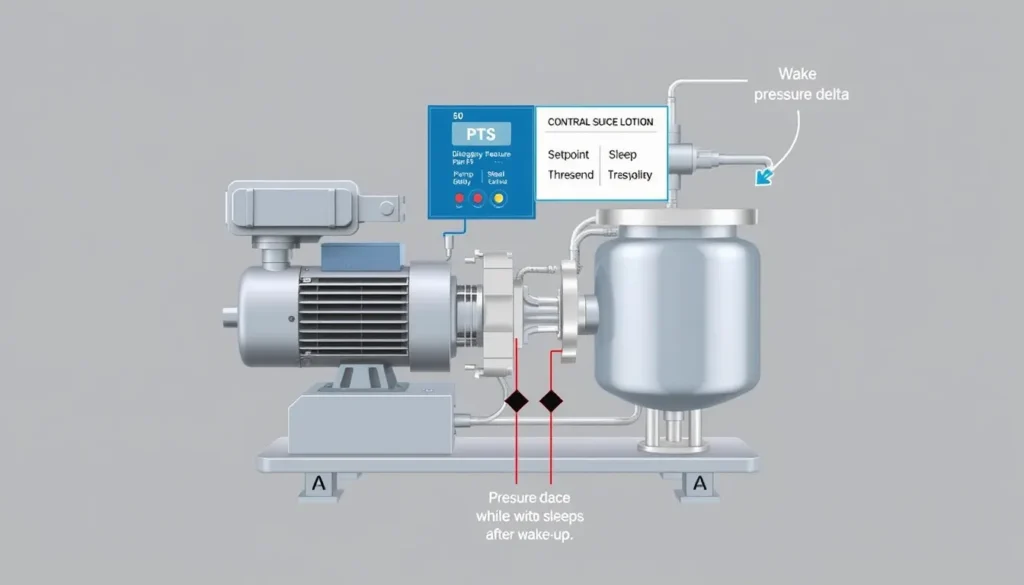
Wake-pressure relationship: P_wake = P_sp – ΔP_wake
Percentage forms: P_wake = P_sp × (1 – r / 100) when r is percent below setpoint; P_wake = P_sp × r / 100 when r is percent of setpoint.
Sleep qualification: f_out < f_sleep for t >= t_sleep.
| Symbol | Meaning | US unit | SI unit |
|---|---|---|---|
| P_wake | Pressure at which the pump is permitted to wake and restart | psi | bar or kPa |
| P_sp | Pressure setpoint held by the pump controller | psi | bar or kPa |
| ΔP_wake | Allowed pressure drop below setpoint before restart | psi | bar or kPa |
| f_out | Controller output frequency or equivalent low-demand signal | Hz | Hz |
| f_sleep | Sleep-entry frequency threshold | Hz | Hz |
| t_sleep | Sleep delay time that the low-demand condition must persist | s | s |
Plain-English restatement: The controller stops the pump when output has stayed below a low-demand threshold long enough, and it restarts when pressure falls by a configured amount below the setpoint.
Overview — What It Is and Why It Matters
Pump sleep mode is a control function used mainly on variable-frequency drives and pressure-boosting controllers. In a constant-pressure system, the drive monitors pressure and adjusts pump speed to hold a setpoint. When demand falls to nearly zero, the pump may continue running at minimum speed against a closed valve or a very small leak. That condition produces little or no useful flow while consuming power and adding heat to the pump and motor. Sleep mode stops the pump after a defined low-demand condition persists. The controller remains energized and monitors pressure, ready to restart the pump when demand returns.
Wake-up pressure is the pressure threshold or pressure drop that tells the controller to restart. It is the counterpart to sleep mode: sleep prevents unnecessary runtime, while wake pressure restores service before users notice an unacceptable pressure loss. Correct settings depend on the pressure setpoint, pressure transducer range, pressure tank volume, piping rigidity, sensor accuracy, and the pump curve. The goal is not to make the pump sleep as quickly as possible. The goal is stable pressure with the fewest unnecessary starts and the shortest unnecessary runtime.
The engineering consequences of poor setup are practical. If sleep is disabled or too difficult to enter, the pump may run for long periods at low speed with no useful flow, wasting energy and possibly overheating water in the pump casing. If sleep is too aggressive, the pump may stop during legitimate small demand and restart repeatedly, causing pressure hunting, contactor wear, motor thermal stress, and noise. Wake pressure that is too close to setpoint produces short cycling. Wake pressure that is too far below setpoint allows a noticeable pressure sag before recovery. Sleep mode therefore sits at the intersection of hydraulics, controls, and equipment protection.

The Method — Derivation and Variants
The basic wake-pressure calculation is a pressure offset from the setpoint. If the controller holds 5.0 bar and the permitted wake drop is 0.7 bar, the pump wakes at 4.3 bar. In US customary form, a 60 psi setpoint with an 8 psi wake drop wakes at 52 psi. This absolute-offset method is intuitive and is common on drives that accept a pressure difference directly.
Some controllers require a percentage rather than an absolute pressure. The two percentage conventions are not interchangeable. If the setting means percent below setpoint, the wake pressure is P_sp × (1 – r/100). For a 5.0 bar setpoint and 14 percent below setpoint, wake pressure is 4.3 bar. If the setting means percent of setpoint, the wake pressure is P_sp × r/100, so the entry for 4.3 bar would be 86 percent. Some drives instead use percent of transmitter full scale. With a 0–10 bar transmitter, 4.3 bar is 43 percent of span. Always identify the comparison basis before entering a number.
Sleep entry is a separate logic. A common method requires the output frequency to remain below a sleep frequency for a sleep delay. The drive may also use low power, low flow, or PID deviation. Low frequency alone is not a flow measurement, so the threshold should be based on observed zero-flow behavior at the required pressure. A minimum run time and minimum off time are often added to prevent immediate restart after stopping and to protect the motor from excessive starts.
| Control condition | US customary form | SI form |
|---|---|---|
| Absolute wake pressure | P_wake (psi) = P_sp (psi) – ΔP_wake (psi) | P_wake (bar) = P_sp (bar) – ΔP_wake (bar) |
| Wake threshold, percent below setpoint | P_wake (psi) = P_sp (psi) × [1 – r/100] | P_wake (bar) = P_sp (bar) × [1 – r/100] |
| Wake threshold, percent of setpoint | P_wake (psi) = P_sp (psi) × r/100 | P_wake (bar) = P_sp (bar) × r/100 |
| Head-to-pressure conversion | psi = ft × SG / 2.31 | kPa = m × SG × 9.81 |
The constants 2.31 and 9.81 come from the weight of water and unit conversion. The 2.31 is the approximate number of feet of water column per psi at specific gravity 1.0. The 9.81 is gravitational acceleration in m/s² for the SI head-to-pressure relationship. These conversions are useful when the pressure sensor reads in psi or bar but the pump and system are described in head.
Worked Example
SI example. A booster set holds 5.0 bar at a variable-speed pump. The wake drop is set to 0.7 bar. The sleep frequency is 32 Hz, the sleep delay is 10 s, the wake delay is 2 s, and the minimum off time is 30 s. The wake pressure is 5.0 – 0.7 = 4.3 bar. The 0.7 bar drop is 14 percent of the setpoint, so a percent-of-setpoint entry would be 86 percent. If the pump remains below 32 Hz for more than 10 s, the drive may enter sleep. When a tap opens and pressure falls to 4.3 bar for 2 s, the drive wakes and ramps the pump. The 30 s minimum off time prevents an immediate restart if pressure briefly recovers and falls again.
US customary example. A 60 psi domestic booster has an 8 psi wake drop. The sleep frequency is 40 Hz, the sleep delay is 12 s, and the wake delay is 2 s. Wake pressure is 60 – 8 = 52 psi. The 8 psi drop is 13.3 percent below setpoint, which equals 86.7 percent of setpoint. Converting to SI, 52 psi is approximately 3.59 bar and 60 psi is approximately 4.14 bar. If the controller expects percent of a 0–100 psi transmitter span, the correct entry for 52 psi is 52 percent, not 86.7 percent. This example shows why the percentage basis must be checked before commissioning.
Calculator
For pressure-head conversions and setpoint checks, use an online total dynamic head calculator. Convert the calculated head to psi or bar, then apply the wake-pressure offset in the drive or controller. Always verify the final value against the manufacturer’s parameter list and the site pressure gauge.
Reference Values & Typical Ranges
| Parameter | Typical starting range | Field note |
|---|---|---|
| Wake pressure drop | 0.5–1.0 bar; about 7–15 psi | Veichi guidance recommends 0.5–1.0 bar below target. Larger drops reduce cycling but allow more pressure sag. |
| Wake drop with pressure tank | 0.8–1.2 bar; about 12–17 psi | Stored water accepts a larger drop and reduces restart frequency. |
| Wake drop without pressure tank | 0.3–0.5 bar; about 4–7 psi | Faster response is needed, but short cycling risk is higher. |
| Sleep frequency | 30–35 Hz on many 50 Hz pump drives | Observe zero-flow operation; do not set below the approved minimum speed merely to force sleep. |
| Sleep delay | 5–15 s | Longer delays avoid false sleep during brief low-flow events. |
| Wake delay | 1–3 s | Prevents nuisance starts from pressure spikes or sensor noise. |
| Minimum off time | 20–60 s | Protect motor and drive from excessive starts; reconcile with service requirements. |
These are commissioning starting points, not universal setpoints. Manufacturer parameters vary by drive model and application macro. Pressure transducers should be scaled, zeroed, and checked against a reference gauge before sleep tuning. Systems with long pipes, large pressure tanks, or multiple pumps may need slower delays and wider wake bands.
Application Guidance
In real systems, sleep mode works best when the hydraulic system stores a small amount of energy or water between the pump and the fixtures. A diaphragm pressure tank stabilizes pressure while the pump is asleep and reduces nuisance starts caused by micro-leaks. Without a tank, any small leak or valve seepage can collapse pressure quickly and wake the pump. In tankless systems, use a smaller wake drop, shorter delays, and careful leak inspection. In systems with a large receiver, a larger wake drop and longer sleep delay are usually acceptable.
- Set the pressure setpoint from fixture requirements, not from the pump’s maximum capability.
- Verify sensor range and signal scaling before changing sleep parameters.
- Observe the pump at true zero flow, then at small flow, before choosing the sleep frequency.
- Use minimum run and minimum off times to limit starts per hour.
- Recheck settings after changing pressure tank precharge, piping, or setpoint.
- For multiple-pump systems, coordinate sleep with lead-lag and alternation logic.
Selection also matters. A pump that is oversized for low demand may operate near shutoff for long periods and reach its minimum speed before useful flow begins. A pump with a flat curve may tolerate pressure-control sleep reasonably well, while a steep-curve pump may show larger pressure swings for the same flow change. The sleep function cannot correct a fundamentally poor pump selection, an undersized pressure tank, or a leaking check valve.
Common Mistakes, Limits & Safety Notes
- Leaving sleep disabled. The pump may run at minimum speed with no useful flow, wasting energy and heating water.
- Setting sleep frequency too low. If the threshold is below what the controller can reach, the pump may never sleep.
- Setting sleep frequency too high. Normal low-flow operation may be mistaken for zero demand, causing nuisance stops.
- Confusing percentage bases. Percent below setpoint, percent of setpoint, and percent of transmitter span produce very different wake pressures.
- Ignoring pressure tank effects. A missing or waterlogged tank can cause rapid cycling and pressure hunting.
- Using sleep to hide leaks. A leaking check valve or fixture can keep waking the pump; fix the leak rather than widening the band excessively.
- Overlooking minimum run and off times. Too many starts per hour can damage motors, contactors, and drives.
- Assuming automatic restart is always safe. Sleep mode can restart the pump without warning. Use lockout and tagout procedures before maintenance, and provide dry-run and overpressure protection.
Sleep mode is not a substitute for a pressure relief device, proper pressure-vessel sizing, or electrical isolation. The drive may remain energized while the pump is asleep. Service personnel must treat the system as capable of automatic restart. In potable-water and HVAC systems, verify that the wake pressure still satisfies the minimum fixture or equipment pressure at the most remote point.
FAQ
What pressure should wake a pump from sleep mode?
A common starting point is 0.5–1.0 bar or about 7–15 psi below the pressure setpoint. For a 5.0 bar setpoint, that means waking near 4.0–4.5 bar. Systems with a pressure tank can often use the wider end, while tankless systems may need a smaller drop and faster response to avoid noticeable pressure sag.
Why does my pump keep starting and stopping after sleep mode?
Short cycling usually means the wake band is too narrow, the sleep delay is too short, the pressure tank is undersized or waterlogged, or there is a leak or leaking check valve. The pump wakes, pressure rises quickly, demand appears satisfied, and the pump sleeps again. Widen the wake drop slightly, add minimum off time, and inspect for leaks.
Can I use pump sleep mode without a pressure tank?
Yes, but it is less forgiving. Without a pressure tank, small leaks or valve seepage can collapse pressure almost instantly and wake the pump repeatedly. Use a smaller wake drop, shorter sleep and wake delays, and a tight piping system. A diaphragm tank is strongly recommended for domestic and small commercial constant-pressure systems.
Why is my pump not going to sleep?
The most common causes are sleep mode being disabled, a sleep frequency set below the controller’s achievable minimum, a sleep delay that is too long, a pressure setpoint that cannot be reached, or real small demand such as a leak. Verify the drive status, sensor reading, output frequency, and whether any minimum-speed limit prevents the sleep threshold from being reached.
What is sleep frequency on a pump VFD?
Sleep frequency is the output-frequency threshold below which the drive begins timing toward sleep. It is not a direct flow measurement. On many 50 Hz pump drives, 30–35 Hz is a useful starting range, but the correct value must be found by observing zero-flow operation at the required pressure. Too low and the pump never sleeps; too high and it stops during legitimate small demand.
Does pump sleep mode really save energy?
Yes, when the pump would otherwise run at minimum speed against a closed valve or very low demand. A pump producing little or no flow still consumes power and adds heat. Sleep mode stops that unnecessary runtime. Savings depend on how long the system is idle, the minimum-speed power draw, and how often the pump restarts. It also reduces noise and mechanical wear.
Is sleep mode safe for submersible pumps?
It can be, provided the motor has adequate cooling, the pump is not allowed to run dry, and restart frequency is limited. Submersible motors may have minimum flow and cooling requirements. Sleep settings should be coordinated with dry-run protection, minimum run time, and manufacturer limits. Repeated rapid starts are especially undesirable for large submersible motors.
How do I test sleep mode after commissioning?
Close all outlets and let pressure stabilize. Observe output frequency and confirm the pump enters sleep after the set delay. Then open a small tap and watch pressure fall to the wake threshold. Confirm the pump restarts after the wake delay, holds pressure, and does not short-cycle. Repeat with a larger tap and check the most remote fixture pressure.
What is the difference between sleep delay and wake delay?
Sleep delay is the time a low-demand condition must persist before the controller stops the pump. Wake delay is the time the pressure must remain below the wake threshold before the controller restarts the pump. Sleep delay prevents false stops from brief low-flow events; wake delay prevents nuisance starts from pressure spikes or sensor noise.


Leave a Reply