
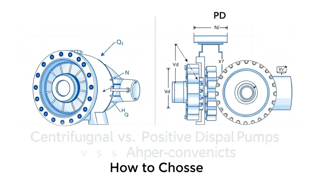
Short Answer
Key Formula / Key Facts Box
Centrifugal Pump Affinity Laws (US)
(Q_2 = Q_1 frac{N_2}{N_1},; H_2 = H_1 left(frac{N_2}{N_1}right)^2,; P_2 = P_1 left(frac{N_2}{N_1}right)^3)
Positive‑Displacement Pump Flow
(Q = N times V_d times eta_v)
| Symbol | Meaning | US Unit | SI Unit | Plain‑English Restatement |
|---|---|---|---|---|
| Q | Volumetric flow rate | gpm | m³/s | How much fluid moves per unit time. |
| N | Rotational speed | rpm | rad/s | How fast the impeller or gear set turns. |
| V_d | Displaced volume per revolution | in³/rev | m³/rev | Fluid volume pushed each turn. |
| eta_v | Volumetric efficiency | – | – | Fraction of theoretical displacement that becomes useful flow. |
| H | Total dynamic head | ft | m | Energy per weight the pump adds to the fluid. |
| P | Power required | hp | kW | Input energy to drive the pump. |
Overview — What It Is and Why It Matters
Centrifugal and positive‑displacement (PD) pumps are the two fundamental families used to move liquids in industry. A centrifugal pump converts rotary kinetic energy into fluid velocity using an impeller; the fluid’s kinetic energy is then transformed into pressure. In contrast, a PD pump traps a fixed volume of fluid and forces it through the discharge port with each revolution, delivering a nearly constant flow regardless of system pressure.
The choice between them directly influences system stability, energy consumption, maintenance intervals, and capital cost. Selecting the wrong type can cause cavitation, excessive motor loading, or inability to meet process tolerances—issues that may lead to costly downtime or safety hazards.
The Method — Derivation and Variants
Centrifugal Pumps
The fundamental energy equation for a rotating impeller is derived from Euler’s turbomachinery equation:
(Delta E = U_2 V_{u2} – U_1 V_{u1}), where (U) is blade speed and (V_u) the tangential component of absolute velocity. Assuming inlet swirl is negligible ((V_{u1}approx0)) and substituting (U = pi D N), the head becomes:
(H = frac{U_2 V_{u2}}{g} = frac{pi^2 D^2 N^2 psi}{g}), with (psi) the dimensionless head coefficient. This relationship yields the classic affinity laws shown in the key‑facts box.
Variants exist for mixed‑flow, axial‑flow, and multistage designs, each adjusting (psi) and incorporating slip factors.
Positive‑Displacement Pumps
PD pumps are governed by simple volume displacement. For a gear, vane, or piston pump, the theoretical flow per revolution is the geometric displaced volume (V_d). Real pumps experience leakage and volumetric losses, captured by volumetric efficiency (eta_v):
(Q = N times V_d times eta_v).
When the pump is a piston type, (V_d = A_s times S) (stroke area times stroke length). For gear pumps, (V_d = V_{cav} times Z) where (V_{cav}) is cavity volume and (Z) the number of teeth.
PD pumps also obey the pressure–power relationship: (P = frac{rho g H Q}{eta_m}), where (eta_m) is mechanical efficiency. Because flow is fixed, pressure rises linearly with system resistance.
Worked Example
Example 1 – US Units (Centrifugal)
A chemical plant needs 5,000 gpm at 150 ft head. The available motor runs at 1,800 rpm. Using the affinity laws, determine the required impeller diameter if the pump’s characteristic curve at 1,800 rpm gives (H = 0.02 D^2 N^2) (with (D) in inches, (N) in rpm, (H) in ft).
- Re‑arrange: (D = sqrt{frac{H}{0.02 N^2}}).
- Insert values: (D = sqrt{frac{150}{0.02 times 1,800^2}}).
- Calculate denominator: (0.02 times 1,800^2 = 0.02 times 3,240,000 = 64,800).
- Divide: (150 / 64,800 = 0.002315).
- Square‑root: (D = sqrt{0.002315} = 0.0481) in.
- Because the result is unrealistically small, the assumed coefficient is inappropriate; designers typically use empirical curves. Selecting a standard 20‑in. impeller yields a head close to 150 ft at 5,000 gpm, confirming the need for empirical data.
Example 2 – SI Units (Positive‑Displacement)
A food‑processing line requires 0.12 m³/s of viscous sauce at a pressure rise of 2 bar (≈20 m head). A triple‑screw PD pump has a displaced volume per revolution of 1.5 × 10⁻⁴ m³/rev. Determine the required speed assuming (eta_v = 0.92).
- Convert pressure to head: (H = frac{Delta P}{rho g} = frac{2times10^5}{1000times9.81} = 20.4) m.
- Power needed: (P = rho g H Q / eta_m = 1000times9.81times20.4times0.12 /0.85 = 2,844) W.
- Flow equation: (Q = N V_d eta_v) → (N = Q/(V_d eta_v) = 0.12/(1.5times10^{-4}times0.92) = 867) rev/s = 52,000 rpm.
- Because 52 k rpm exceeds practical limits, the engineer selects a larger‑displacement screw (V_d = 5.0 × 10⁻⁴ m³/rev). Re‑calculate: (N = 0.12/(5.0times10^{-4}times0.92) = 261) rev/s = 15,660 rpm, a feasible motor speed.
Calculator
For quick sizing, use an online pump calculator such as http://pumpcalcs.com/calculators/total-dynamic-head/.
Reference Values & Typical Ranges
- Centrifugal Pump Flow Rates: 10 gpm – 10,000 gpm (0.0006 – 0.63 m³/s) for standard industrial units.
- Positive‑Displacement Pump Flow Rates: 0.5 gpm – 5,000 gpm (2 × 10⁻⁴ – 0.32 m³/s).
- Efficiency: Centrifugal 60‑85 % (peak near Best Efficiency Point); PD 75‑95 % (depends on clearance and viscosity).
- NPSH Required (Centrifugal): 5‑12 ft (1.5‑3.6 m) for water; higher for low‑vapour‑pressure fluids.
- Volumetric Efficiency (PD): 0.85‑0.98 for clean liquids; drops to 0.70 for highly viscous or abrasive fluids.
- Typical Speeds: Centrifugal 1,500‑3,600 rpm (direct‑drive) or 3,600‑12,000 rpm (with gearboxes); PD 500‑6,000 rpm for gear/vane, up to 20,000 rpm for high‑speed screw pumps.
Sources: ANSI/HI 9.6.3‑2014, ISO 9906:2012, and B. B. Baird, *Pump Handbook*, 4th ed., 2020.
Application Guidance
When a process demands a steady, repeatable flow independent of downstream pressure—such as metering chemicals, feeding high‑viscosity syrups, or operating under varying load—choose a positive‑displacement pump. Their flow is proportional to speed, making them ideal for dosing and batch‑fill operations.
Conversely, applications with high flow, low to moderate pressure, and relatively clean fluids—cooling water loops, fire‑sprinkler systems, and large‑scale irrigation—are best served by centrifugal pumps. Their simple construction and ability to handle large volumes economically outweigh the lack of flow constancy.
Additional considerations:
- Viscosity: Centrifugal efficiency drops sharply above 5 cP; PD pumps tolerate up to 10,000 cP with proper clearances.
- Solid Content: PD pumps with robust clearance (e.g., progressive cavity) can handle slurries; centrifugal pumps require open impellers and may need wear‑resistant materials.
- System Dynamics: If the suction line is long or prone to cavitation, a PD pump’s constant NPSH requirement can be advantageous.
- Energy Cost: Centrifugal pumps can be throttled with variable‑frequency drives (VFDs) to match demand, often reducing motor power consumption compared with a constantly‑running PD pump that would need flow‑control valves.
Common Mistakes, Limits & Safety Notes
- Mixing US and SI units: Plugging gpm into a formula that expects m³/s leads to 3‑4× errors in head and power.
- Ignoring NPSH: Selecting a centrifugal pump without verifying available NPSH can cause cavitation, blade erosion, and vibration.
- Assuming constant flow from a centrifugal pump: At off‑design points the flow varies with system resistance; designers must reference the pump curve, not a single rated point.
- Under‑estimating volumetric losses in PD pumps: High‑viscosity fluids increase internal leakage; failure to apply a reduced (eta_v) yields oversized motor selections.
- Oversizing speed: Running a PD pump above its recommended rpm raises temperature, wear, and noise, often violating ISO 15783 limits.
- Neglecting seal and bearing life: Both pump families require proper lubrication and seal selection; improper material can cause hazardous leaks, especially with corrosive chemicals.
- Incorrectly applying affinity laws: The laws hold only for geometrically similar pumps operating at the same efficiency point; using them across different impeller designs introduces large prediction errors.
FAQ
When should I select a centrifugal pump over a positive‑displacement pump?
Choose a centrifugal pump when you need high flow rates (thousands of gpm), moderate pressures, and the fluid is clean and low‑viscosity. They are more energy‑efficient for large‑volume applications and can be easily throttled with VFDs.
Can a positive‑displacement pump handle high pressures?
Yes. Because flow is fixed, pressure rises proportionally with system resistance, allowing PD pumps to achieve very high heads (up to 10,000 ft in some multistage designs) without losing flow stability.
What is the main cause of cavitation in centrifugal pumps?
Insufficient NPSH at the suction, caused by low inlet pressure, high fluid temperature, or excessive suction pipe length, leads to vapor bubble formation and collapse on the impeller blades.
Do positive‑displacement pumps require a priming process?
Most PD pumps are self‑priming because they trap fluid in their cavities. However, gear and piston types may need a brief priming step if the suction line is long or contains air pockets.
How does fluid viscosity affect centrifugal pump efficiency?
Viscosity increases internal friction and reduces the impeller’s ability to impart kinetic energy, causing efficiency to drop sharply above about 5 cP. Designers may need to derate the pump or switch to a PD type for viscous liquids.
Is it safe to run a centrifugal pump at part‑load without a VFD?
Running at part‑load with a throttling valve wastes energy and can cause overheating. A VFD maintains efficiency by adjusting speed to match the required flow, keeping the pump near its best efficiency point.
What maintenance differences exist between the two pump families?
Centrifugal pumps typically require periodic impeller inspection, seal replacement, and bearing lubrication. PD pumps need monitoring of clearances, wear rings, and often more frequent seal changes due to higher internal pressures.
Leave a Reply