
Short Answer
How to Use This Reference
Each table on this page corresponds to a specific calculation elsewhere on this site—friction loss, NPSH, TDH, and pipe sizing all draw on the values below. Where a table’s values are used inside one of the site’s calculators, that calculator is linked directly beneath the table. All values here are cross-checked against standard engineering references (Crane TP-410, Cameron Hydraulic Data, ASHRAE, and the cited standards below); where a value is commonly quoted as a range rather than a single number, the range is shown, since actual material and fluid properties vary with manufacturing tolerance, age, and exact formulation.
Unit Conversion Tables
Flow Rate
| From | To | Multiply by |
|---|---|---|
| US gpm | L/min | 3.785412 |
| US gpm | L/s | 0.0630902 |
| US gpm | m³/h | 0.227125 |
| US gpm | m³/min | 0.00378541 |
| m³/h | US gpm | 4.402868 |
| L/min | US gpm | 0.264172 |
| L/s | US gpm | 15.850323 |
Head and Pressure
| From | To | Multiply by |
|---|---|---|
| ft of water (60°F) | psi | 0.4331 |
| psi | ft of water (60°F) | 2.3086 |
| m of water (4°C) | kPa | 9.80665 |
| kPa | m of water (4°C) | 0.101972 |
| bar | psi | 14.5038 |
| psi | bar | 0.068948 |
| atm | psi | 14.696 |
| atm | kPa | 101.325 |
| psi | kPa | 6.89476 |
Note: the ft-of-water ↔ psi conversion depends slightly on the fluid’s temperature and specific gravity (water density varies with temperature—see the Water Properties table below). The 2.3086 factor (commonly rounded to 2.31) assumes water at approximately 60°F and SG = 1.0; for other fluids or temperatures, divide by the actual specific gravity.
Power
| From | To | Multiply by |
|---|---|---|
| HP | kW | 0.745700 |
| kW | HP | 1.341022 |
| HP | ft·lb/s | 550 |
| kW | BTU/h | 3412.14 |
Viscosity
| From | To | Multiply by |
|---|---|---|
| centipoise (cP) | Pa·s | 0.001 |
| centipoise (cP) | centistoke (cSt) | divide by fluid SG |
| centistoke (cSt) | mm²/s | 1 (identical units) |
Temperature
$$°F = (°C \times \tfrac{9}{5}) + 32 \qquad °C = (°F – 32) \times \tfrac{5}{9} \qquad K = °C + 273.15$$
Use the Flow Unit Converter · Use the Pressure Unit Converter · Use the Head ↔ Pressure Converter · Use the HP ↔ kW Converter
Water Properties by Temperature
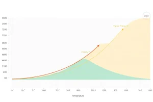
Density, vapor pressure, and dynamic viscosity of water at atmospheric pressure. These values are the basis for every NPSH and friction-loss calculation involving water or water-based fluids at non-standard temperatures—vapor pressure in particular is the value most often overlooked when checking NPSH on a hot-water or steam-condensate application.
| Temp (°F) | Temp (°C) | Density (lb/ft³) | Density (kg/m³) | Vapor pressure (psia) | Vapor pressure (kPa) | Viscosity (cP) |
|---|---|---|---|---|---|---|
| 32 | 0 | 62.42 | 999.8 | 0.089 | 0.61 | 1.79 |
| 50 | 10 | 62.41 | 999.7 | 0.178 | 1.23 | 1.31 |
| 60 | 15.6 | 62.37 | 999.1 | 0.256 | 1.76 | 1.12 |
| 70 | 21.1 | 62.30 | 998.0 | 0.363 | 2.50 | 0.98 |
| 80 | 26.7 | 62.22 | 996.6 | 0.507 | 3.50 | 0.86 |
| 100 | 37.8 | 62.00 | 993.0 | 0.950 | 6.55 | 0.68 |
| 120 | 48.9 | 61.71 | 988.6 | 1.692 | 11.67 | 0.56 |
| 140 | 60.0 | 61.38 | 983.3 | 2.888 | 19.92 | 0.47 |
| 160 | 71.1 | 61.00 | 977.1 | 4.739 | 32.68 | 0.40 |
| 180 | 82.2 | 60.57 | 970.1 | 7.510 | 51.77 | 0.36 |
| 200 | 93.3 | 60.11 | 962.9 | 11.526 | 79.5 | 0.31 |
| 212 | 100.0 | 59.83 | 958.4 | 14.696 | 101.3 | 0.28 |
Critical NPSH note: vapor pressure rises steeply and non-linearly with temperature—it roughly quadruples between 60°F and 140°F. A pump correctly sized for cold water NPSH can cavitate on the same piping at elevated temperature purely from this effect. Always look up vapor pressure at the actual operating temperature, not at 60°F “for simplicity.”
Use the Water Properties Lookup Calculator — interpolates between these values automatically.
Steel Pipe Schedule Chart
Nominal pipe size (NPS), outside diameter (OD), and wall thickness/inside diameter (ID) for Schedule 40 and Schedule 80 steel pipe—the two most common schedules in pump piping.
| NPS (in) | OD (in) | Sch 40 wall (in) | Sch 40 ID (in) | Sch 80 wall (in) | Sch 80 ID (in) |
|---|---|---|---|---|---|
| 1/2 | 0.840 | 0.109 | 0.622 | 0.147 | 0.546 |
| 3/4 | 1.050 | 0.113 | 0.824 | 0.154 | 0.742 |
| 1 | 1.315 | 0.133 | 1.049 | 0.179 | 0.957 |
| 1-1/4 | 1.660 | 0.140 | 1.380 | 0.191 | 1.278 |
| 1-1/2 | 1.900 | 0.145 | 1.610 | 0.200 | 1.500 |
| 2 | 2.375 | 0.154 | 2.067 | 0.218 | 1.939 |
| 2-1/2 | 2.875 | 0.203 | 2.469 | 0.276 | 2.323 |
| 3 | 3.500 | 0.216 | 3.068 | 0.300 | 2.900 |
| 4 | 4.500 | 0.237 | 4.026 | 0.337 | 3.826 |
| 6 | 6.625 | 0.280 | 6.065 | 0.432 | 5.761 |
| 8 | 8.625 | 0.322 | 7.981 | 0.500 | 7.625 |
| 10 | 10.750 | 0.365 | 10.020 | 0.593 | 9.564 |
| 12 | 12.750 | 0.375 | 12.000 | 0.687 | 11.376 |
Why ID matters more than nominal size: friction loss and velocity calculations depend on actual inside diameter, not the nominal size stamped on the pipe. A “2-inch” Schedule 80 pipe has a meaningfully smaller bore (1.939 in) than a “2-inch” Schedule 40 pipe (2.067 in)—always pull the actual ID for the specific schedule in use before calculating velocity or friction loss.
Use the Pipe Schedule Lookup Calculator · Use the Pipe Size & Velocity Calculator
Pipe Roughness Values
Absolute roughness (ε) values used in the Darcy-Weisbach friction factor calculation (Colebrook or Swamee-Jain equations). These are representative values for new or reasonably well-maintained pipe—roughness increases with age, scaling, and corrosion, sometimes substantially.
| Material | ε (mm) | ε (ft) | Typical condition |
|---|---|---|---|
| Drawn copper/brass tubing | 0.0015 | 0.000005 | New |
| PVC / plastic pipe | 0.0015–0.007 | 0.000005–0.00002 | New |
| HDPE | 0.007 | 0.00002 | New |
| Commercial steel / wrought iron | 0.045 | 0.00015 | New |
| Asphalt-coated cast iron | 0.12 | 0.0004 | New |
| Galvanized iron | 0.15 | 0.0005 | New |
| Cast iron (uncoated) | 0.26 | 0.00085 | New |
| Concrete | 0.3–3.0 | 0.001–0.01 | Depends on finish/formwork |
| Riveted steel | 0.9–9.0 | 0.003–0.03 | Wide range by construction |
Aged pipe caution: commercial steel pipe in older potable water or process service can develop roughness several times its new-pipe value due to scaling and tuberculation. For systems with pipe older than roughly 15–20 years and no internal lining, consider using an aged-pipe roughness estimate or verifying with a field friction test rather than relying solely on new-pipe values.
Use the Friction Loss Calculator (Darcy-Weisbach) — includes this roughness table as a built-in material selector.
Hazen-Williams C Values
C-factors for the Hazen-Williams friction loss equation, shown for both new pipe and a typical aged/design value that accounts for expected roughening over service life.
| Material | C (new) | C (design/aged) |
|---|---|---|
| PVC / plastic | 150 | 150 |
| HDPE | 150 | 145 |
| Copper | 140 | 130 |
| New welded/seamless steel | 140 | 100 |
| New cast iron | 130 | 100 |
| Cement-lined ductile iron | 140 | 130 |
| Concrete | 140 | 120 |
| Asbestos cement | 140 | 120 |
| Old, unlined cast iron (tuberculated) | — | 60–80 |
Why the “design” column matters: using new-pipe C values for a system’s entire service life systematically understates friction losses as the pipe ages. Most municipal and industrial design practice uses the lower “design” value specifically to build in margin for the pipe’s expected condition partway through its service life—this is a deliberate design choice, not a measurement of any single point in time.
Use the Friction Loss Calculator (Hazen-Williams) — includes a built-in Darcy-Weisbach comparison to flag when Hazen-Williams may not be the appropriate method (see the validity limits noted in the System Design).
K-Factor Table for Valves and Fittings
Representative resistance coefficients (K) for common valves and fittings, used to calculate minor (fitting) losses: $h_f = K \times \dfrac{v^2}{2g}$. Actual K values vary by manufacturer, size, and specific design—treat these as planning-level estimates and consult the manufacturer’s data for final design on critical applications.
| Fitting / valve | Typical K |
|---|---|
| 90° standard elbow | 0.75–0.9 |
| 90° long-radius elbow | 0.45 |
| 45° elbow | 0.35–0.42 |
| Tee, flow through run | 0.4 |
| Tee, flow through branch | 1.0–1.8 |
| Gate valve, fully open | 0.15–0.2 |
| Globe valve, fully open | 6.0–10 |
| Ball valve, fully open | 0.05 |
| Butterfly valve, fully open | 0.3–0.5 |
| Swing check valve | 2.0–2.5 |
| Sharp-edged pipe entrance | 0.5 |
| Well-rounded pipe entrance | 0.04 |
| Pipe exit (to a large reservoir) | 1.0 |
Use the K-Factor & Equivalent Length Calculator — sums multiple fittings automatically for a full suction or discharge line minor-loss calculation.
Specific Gravity and Viscosity of Common Fluids
Representative values at approximately 60–68°F (15.6–20°C) unless otherwise noted. Both specific gravity and viscosity are strongly temperature-dependent for most non-aqueous fluids—these figures are starting points, not substitutes for the actual fluid’s data sheet.
| Fluid | Specific gravity | Viscosity (cP) |
|---|---|---|
| Water (fresh) | 1.00 | 1.0–1.1 |
| Seawater | 1.025 | ~1.05 |
| Gasoline | 0.72–0.74 | 0.5–0.6 |
| Diesel fuel | 0.82–0.86 | 2–4 |
| SAE 30 motor oil | 0.87–0.89 | 200–400 (steep temperature dependence) |
| Light crude oil | 0.80–0.88 | 5–100+ (wide field variation) |
| Ethylene glycol (pure) | 1.11 | 16–20 |
| Propylene glycol (pure) | 1.04 | 40–60 |
| Glycerin (pure) | 1.26 | 1,000–1,500 |
| Sulfuric acid (98%) | 1.84 | ~24 |
| Sodium hydroxide solution (50%) | 1.53 | ~78 |
| Milk (whole) | 1.03 | ~2.0 |
Glycol note: propylene and ethylene glycol/water mixtures (common in HVAC hydronic freeze protection) change specific heat, density, and viscosity depending on concentration—see the HVAC Hydronic Pump Sizing calculator for a built-in glycol correction rather than using pure-glycol values for a mixed solution.
Atmospheric Pressure by Altitude
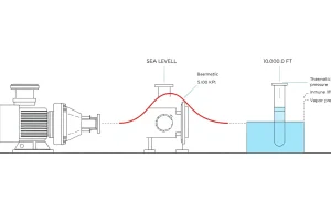
Standard atmospheric pressure decreases with elevation, directly reducing available NPSH for any suction-lift application. These values follow the standard barometric formula and represent typical conditions—actual local barometric pressure varies with weather and should be used for precision work.
| Altitude (ft) | Altitude (m) | Pressure (psia) | Pressure (kPa) |
|---|---|---|---|
| 0 (sea level) | 0 | 14.696 | 101.33 |
| 1,000 | 305 | 14.18 | 97.7 |
| 2,000 | 610 | 13.66 | 94.2 |
| 3,000 | 914 | 13.17 | 90.8 |
| 4,000 | 1,219 | 12.68 | 87.5 |
| 5,000 | 1,524 | 12.23 | 84.3 |
| 6,000 | 1,829 | 11.78 | 81.2 |
| 7,000 | 2,134 | 11.34 | 78.2 |
| 8,000 | 2,438 | 10.91 | 75.3 |
| 9,000 | 2,743 | 10.50 | 72.4 |
| 10,000 | 3,048 | 10.10 | 69.7 |
Why this matters for sizing: a well pump or booster system designed at sea level and then installed at 5,000 ft elevation loses roughly 2.5 psi (about 5.8 ft of head) of available NPSH purely from the altitude change—enough, on a marginal design, to push a previously adequate system into cavitation. Always use the actual site elevation, not sea-level assumptions, in any NPSH calculation.
Use the NPSH Available Calculator — includes this altitude table as a built-in lookup.
Pump Standards Explained
A plain-language guide to the standards referenced throughout this site’s calculators and articles.
| Standard | Full name | What it covers | Typical users |
|---|---|---|---|
| ANSI/HI 14.1–14.2 | Centrifugal Pump Nomenclature, Definitions, Applications, and Operation | Terminology, definitions, and general application guidance—the vocabulary the rest of the pump industry builds on | General reference across all pump industries |
| ANSI/HI 9.6.1–9.6.7 | Pump Tests and Acceptance Criteria | Testing methods and acceptance tolerances for verifying a pump meets its stated performance | Pump manufacturers, testing labs, acceptance testing |
| ANSI/HI 9.6.4 | Rotodynamic Pumps for Vibration Measurements and Allowable Values | Standardized vibration measurement points and severity guidance for pumps specifically (distinct from the more general ISO 10816/20816 series) | Reliability engineers, vibration analysts |
| API 610 | Centrifugal Pumps for Petroleum, Petrochemical, and Natural Gas Industries | A severe-duty construction and testing specification—heavier construction margins, more rigorous testing, and features (like specific seal chamber and baseplate requirements) aimed at continuous, high-criticality service | Oil & gas, refining, petrochemical |
| ASME/ANSI B73.1 | Specification for Horizontal End Suction Centrifugal Pumps | A dimensional standard (the “ANSI pump” designation)—defines standard mounting dimensions so pumps from different manufacturers are interchangeable on the same baseplate, rather than specifying construction ruggedness the way API 610 does | Chemical process industry, general industrial |
| ISO 5199 | Technical Specifications for Centrifugal Pumps—Class II | Broadly comparable in intent to API 610 but generally less stringent—a common international/European alternative for process pumps outside the oil & gas sector | International and European process industry |
| NFPA 20 | Installation of Stationary Pumps for Fire Protection | Governs fire pump selection, listing, installation, and acceptance testing—compliance is typically mandatory where fire protection systems are code-required | Fire protection engineers, AHJs, life-safety design |
| AWWA standards (e.g., E101, E103) | Various, covering vertical turbine and other pump types for water utility service | Municipal water supply pump design and procurement standards | Water utilities, municipal engineers |
| NEMA MG1 | Motors and Generators | Motor performance, frame sizes, service factor, and efficiency classification (see the Motors & Energy pillar for detail) | Motor manufacturers, electrical engineers |
A frequent point of confusion: API 610 and ASME B73.1 are sometimes discussed as if they were competing options for the same decision, but they answer different questions—B73.1 standardizes dimensions and interchangeability; API 610 specifies construction robustness and testing rigor for severe service. A pump can, and often does, meet both simultaneously depending on the application.
Related Calculators and Further Reading
Recommended Calculators on PumpCalcs.com
- Flow Unit Converter · Pressure Unit Converter · HP ↔ kW Converter · Head ↔ Pressure Converter
- Water Properties Lookup — interpolated density, vapor pressure, and viscosity at any temperature.
- Pipe Schedule Lookup — full schedule and dimension lookup beyond the abbreviated table above.
- Friction Loss Calculator (Darcy-Weisbach) and Friction Loss Calculator (Hazen-Williams) — both draw directly on the roughness and C-value tables above.
- K-Factor & Equivalent Length Calculator
- NPSH Available Calculator — includes the altitude and water vapor-pressure tables as built-in lookups.
Primary Sources
- Crane Technical Paper 410 (TP-410): Flow of Fluids Through Valves, Fittings, and Pipe. The standard industry reference for K-factors and friction methodology.
- Cameron Hydraulic Data Book (Flowserve): pipe, fluid property, and general hydraulic reference tables.
- ASME B36.10 / B36.19: Welded and Seamless Wrought Steel Pipe / Stainless Steel Pipe—source standards for the pipe schedule dimensions above.
- NIST / ASHRAE steam and water property tables: source basis for the water properties table above.
- U.S. Standard Atmosphere (1976): basis for the altitude-pressure table.
Verification and Disclaimer
Data verification: All tables on this page are cross-checked against at least two independent published sources (Crane TP-410, Cameron Hydraulic Data, ASME pipe standards, and standard steam/water property tables) as part of this site’s verification protocol. Where a property varies by manufacturer, formulation, or specific test condition, a representative range is shown rather than a false single-value precision.
Recommended use: These tables are suitable for preliminary design, estimation, and educational use. For final design, procurement specifications, or code-compliance documentation, verify current values against the specific manufacturer’s data sheet and the current published edition of the applicable standard—standards are periodically revised, and this page reflects general, commonly-applied guidance rather than a specific edition date.
For corrections or feedback: See the Contact page. If you identify a value that differs from a current authoritative source, please let us know—we verify and publicly log all corrections.
Last updated: July 2026 | Reviewed by: [PE Reviewer Name, [State] PE License [Number]] | Reading time: ~14 minutes
FAQ
What is the most reliable source for water property data?
The IAPWS‑IF97 formulation is the internationally accepted reference for temperature‑dependent water and steam properties.
How often should pipe schedule selections be reviewed?
Whenever there is a change in operating temperature, pressure, or flow velocity—typically during plant turnarounds or equipment retrofits.
Can I use a single standard for all pump installations?
No. Different industries require specific standards such as ASME B31.3 for process plants, ASME B31.1 for power generation, and API 610 for centrifugal pumps.
Why is NPSHA often lower than expected?
Friction losses in suction piping, elevation differences, and high fluid vapor pressure all reduce the net positive suction head available.
What role do digital twins play in pump engineering?
Digital twins combine real‑time sensor data with reference models of units, fluid properties, and piping to enable predictive maintenance and performance optimization.
Leave a Reply