
Short Answer
The Systematic Approach to Pump Troubleshooting
Cheap and Easy First
The single most valuable troubleshooting habit is resisting the urge to disassemble the pump before ruling out everything upstream and downstream of it. In rough order of investigation cost:
- Verify power and control status — is the pump actually receiving power, and is the control system (float switch, pressure switch, PLC) actually calling for it to run?
- Verify valve line-up — are suction and discharge valves in their correct positions? A closed or partially closed valve is the single most common cause of “the pump stopped working” service calls.
- Verify rotation direction — especially after any electrical work; a three-phase motor rewired or reconnected incorrectly will run backward.
- Check gauges and instrumentation — what do suction pressure, discharge pressure, and flow (if metered) actually show right now, compared to normal?
- Listen and feel — unusual noise, vibration, or heat at the pump and motor casing, bearing housings, and piping.
- Only then — proceed to opening the pump casing, pulling the impeller, or removing the motor for internal inspection.
This sequence matters because the cheap checks catch a large share of real-world service calls (closed valves, tripped breakers, lost prime, clogged strainers) without a single tool beyond a flashlight and a multimeter, while the expensive checks (teardown, bearing replacement, impeller inspection) are reserved for when the cheap checks come back clean.
Master Symptom → Cause Reference
Use this table as a starting map. Each row links to the detailed diagnostic sequence further down this page.
| Symptom | Most likely causes (roughly in order of frequency) | Check first |
|---|---|---|
| No flow at all | Lost prime · wrong rotation · closed/blocked valve · broken shaft coupling · impeller loose on shaft | Prime status, rotation direction, valve positions |
| Low flow / low pressure | Worn impeller or wear rings · clogged strainer · excessive friction loss · partial cavitation · air leak on suction | Strainer, suction gauge reading, valve throttling |
| Noisy — rattling/gravel sound | Cavitation (NPSH deficit) | NPSH calculation, suction gauge |
| Noisy — similar rattle, intermittent | Air entrainment (leak or vortexing) | Suction fittings, tank level/submergence |
| Noisy — grinding/rumbling at bearing | Bearing wear or lubrication failure | Bearing temperature, grease condition |
| Noisy — crackling at very low flow | Internal recirculation (operating far below BEP) | Actual flow vs. minimum continuous flow rating |
| Noisy — sharp bang, especially at valve closure | Water hammer / surge | Valve closure speed, check valve slam |
| Excessive vibration, 1× running speed | Unbalance | Vibration spectrum |
| Excessive vibration, 2× running speed | Misalignment | Alignment check |
| Casing overheating | Running below minimum flow / dead-heading | Actual flow vs. minimum flow curve |
| Bearing overheating | Over/under-lubrication, misalignment, contamination | Grease condition, alignment |
| Motor overheating | Voltage imbalance, single-phasing, poor ventilation, runout overload | Voltage per phase, ambient temperature, actual amp draw vs. FLA |
| Motor trips breaker on start | Locked rotor / mechanical bind | Manual shaft rotation check (power off) |
| Motor trips breaker after running a while | Overload from runout, voltage imbalance, undersized thermal element | Amp draw vs. nameplate FLA over time |
| Short cycling (starts/stops rapidly) | Waterlogged pressure tank, narrow pressure switch spread, check valve failure | Tank air charge, pressure switch settings |
No Flow: Pump Not Pumping
Diagnostic Sequence
- Confirm the motor is actually running — check for rotation at the coupling or shaft, listen for the motor hum, verify at the breaker/starter that power is present and the overload has not tripped.
- Verify rotation direction. A centrifugal pump running backward produces drastically reduced or near-zero head—this is easy to overlook after any rewiring, breaker replacement, or motor swap where phase order can be accidentally reversed.
- Check prime. If the casing has lost its prime (air has entered and displaced the liquid), a standard centrifugal pump cannot generate flow. See the priming diagnostic guidance for the common causes of lost prime.
- Check valve positions. Confirm the suction valve is fully open and the discharge valve is not fully closed or obstructed—an easy thing to overlook after any nearby maintenance work.
- Check for a clogged suction strainer or foot valve. A fully blocked strainer stops flow entirely, not just reduces it.
- Check for an impeller loose on the shaft. If a keyway, set screw, or impeller nut has failed, the shaft can spin while the impeller does not rotate with it (or rotates only partially)—the motor runs, the shaft turns, but no useful work is done. This typically requires opening the pump to confirm.
- Check for a severely air-locked system. A high point in the piping that traps a large air pocket can completely block flow even with the pump properly primed at the casing.
- Check whether the system head exceeds the pump’s shutoff head. If the system was modified (added elevation, a closed valve elsewhere, new restriction) such that the required head now exceeds what the pump can produce even at zero flow, the pump will run but deliver nothing. Compare the system’s static head to the pump’s published shutoff head.
Low Flow or Low Pressure
The Twelve Most Common Causes
- Partially clogged suction strainer or foot valve — restricts inflow without fully blocking it.
- Worn impeller or wear rings — increased internal clearances allow discharge fluid to slip back to the suction side internally, reducing net delivered flow even though the impeller still appears to be turning normally.
- Wrong impeller trim installed — a smaller-diameter impeller than the application was designed for produces a lower curve across the board.
- Speed lower than rated — incorrect VFD frequency setting, wrong pulley ratio on a belt-driven pump, or a motor wired for the wrong voltage/frequency running slow.
- Excessive system friction losses — pipe scaling or fouling, an undersized pipe, or a partially closed valve that wasn’t accounted for in the original design.
- Partial cavitation — an NPSH margin that is thin but not zero can cause partial vapor formation that reduces effective flow without the dramatic noise of full cavitation. See Cavitation vs. Air Entrainment below.
- Air leak on the suction side — reduces volumetric efficiency without necessarily stopping flow entirely; often accompanied by intermittent noise (see the Noise section).
- Wrong rotation direction — some pump designs (particularly certain self-priming and PD types) produce reduced but non-zero flow when run backward, rather than the complete stoppage typical of a standard centrifugal.
- Internal recirculation from worn wear-ring clearances — a specific case of cause #2, called out separately because it is frequently missed: the clearance increases gradually over years, so performance degrades slowly enough that operators may not notice until flow has dropped substantially.
- System curve has shifted — a valve left partially closed, a new branch added downstream, or increased elevation moves the duty point to a lower flow/higher head intersection than the system was originally designed to deliver.
- Fluid viscosity higher than design basis — colder-than-expected fluid temperature, or an unplanned change in the fluid itself, increases friction losses and can de-rate centrifugal pump performance beyond what the design curve assumed.
- Unequal parallel pump operation — when two or more pumps run in parallel with mismatched or degraded curves, one pump can effectively “starve” the system of its expected contribution, or in extreme mismatch cases even allow partial backflow through the weaker unit. See Pumps in Series vs. Parallel for the underlying curve mechanics.
Diagnostic Order
Check the suction strainer and suction gauge reading first (cheapest, fastest). Compare actual discharge pressure and flow against the pump’s published curve at the current operating point—a significant deviation confirms that something is wrong even before you know what. Then work through causes 2–12 roughly in order of inspection cost, verifying NPSH margin with the NPSH Available Calculator before assuming cavitation, and checking valve positions and system configuration before assuming internal pump wear.
<a name=”noise”></a>
Unusual Noise: Identifying the Source
Pump noise is diagnostically useful because different causes produce recognizably different sound characteristics, even before any instrumentation is used.
| Sound character | Likely cause | Distinguishing detail |
|---|---|---|
| Rattling, like gravel moving through the pump, fairly continuous | Cavitation | Consistent regardless of tank level; correlates with a calculated NPSH margin deficit; often worsens with higher flow demand (which increases NPSH required) |
| Similar rattling, but intermittent or tied to tank level changes | Air entrainment | May reduce or stop if a suction-side vent or leak is closed, or if submergence at the suction inlet increases |
| Popping or crackling, specifically at very low flow | Internal recirculation | Occurs when the pump is operated well below its minimum continuous stable flow, often near shutoff |
| Grinding or rumbling, localized to a bearing housing | Bearing wear or lubrication failure | Often accompanied by elevated bearing temperature; may increase in pitch as damage progresses |
| Sharp metallic scraping, may vary with shaft position | Mechanical rub (impeller-to-casing contact) | Frequently follows wear-ring failure or a developing misalignment condition |
| Sharp bang or thud, tied to a valve closing or pump stopping | Water hammer / surge | Not continuous; correlates with specific transient events rather than steady operation |
Cavitation vs. Air Entrainment: Telling Them Apart
These two conditions sound similar and are frequently confused, but they have different causes and different fixes.
Cavitation
Cavitation occurs when the local pressure inside the pump (typically at the impeller eye, where velocity is highest and pressure lowest) drops below the fluid’s vapor pressure, causing the liquid itself to flash to vapor. As those vapor bubbles move to a higher-pressure region downstream, they collapse violently, producing the characteristic noise and, over time, pitting damage to the impeller and casing.
Cavitation is fundamentally an NPSH problem — available suction pressure is insufficient for the flow being demanded. It will not go away on its own and will not respond to fixing a leak, because there is no leak to fix; the fluid itself is the “gas” being generated internally.
Air Entrainment
Air entrainment is the ingestion of actual air (or another gas) into the suction stream from an external source—a leaking fitting, a worn seal on the suction side of the pump, or a vortex forming at the suction inlet due to insufficient submergence. The symptoms can sound very similar to cavitation because both involve gas bubbles collapsing or moving through the pump, but the source of the gas is entirely different.
How to Tell Them Apart in the Field
| Test | Cavitation | Air entrainment |
|---|---|---|
| Calculate NPSH margin using the NPSH Available Calculator | Margin is thin or negative | Margin is typically healthy |
| Effect of raising suction tank level / submergence | No change | Noise typically reduces or stops |
| Effect of closing a suspected suction-side leak or vent | No change | Noise typically stops |
| Sight glass or clear section on suction line (if available) | Usually not visibly different | May show visible foam or bubbles |
| Consistency across operating conditions | Often worse at higher flow (higher NPSH required) | Often tied to tank level, weather (thermal expansion opening a fitting), or specific valve positions |
Practical approach: run the NPSH calculation first. If the margin is clearly healthy (well above the 1.1–1.5× guidance discussed in the Pump Hydraulics pillar), the problem is very unlikely to be cavitation, and attention should shift to finding an air leak or a submergence/vortexing issue. If the margin is thin or negative, address the NPSH deficit first—no amount of leak-chasing will fix a genuine cavitation problem.
Excessive Vibration
Vibration troubleshooting benefits enormously from knowing which frequency the vibration occurs at relative to running speed, since different mechanical faults produce distinctly different frequency signatures. See the Installation & Maintenance for the full explanation of measurement practice and ISO 10816/20816 severity zones; the table below focuses specifically on using frequency pattern for diagnosis.
| Frequency pattern | Likely cause | What to check |
|---|---|---|
| 1× running speed, dominant | Unbalance (most common single cause) | Impeller cleanliness/damage, foreign material buildup on one side of the impeller |
| 2× running speed, often with high axial component | Misalignment | Coupling alignment per the alignment tolerance guidance |
| Multiples of running speed (harmonics) | Looseness, bent shaft, or mechanical rubbing | Foundation bolts, coupling condition, soft foot |
| Non-integer multiples of running speed | Bearing defect (race or rolling element damage) | Requires spectral (FFT) analysis; correlates with bearing age and lubrication history |
| Blade-pass frequency (running speed × number of vanes) | Hydraulic effects, often tied to operating away from BEP | Actual flow vs. BEP flow, impeller-to-cutwater clearance |
| Random, broadband | Cavitation | See the cavitation diagnostic above |
A rising trend matters more than a single absolute reading. A vibration level that has doubled over several months, even if it remains within a nominally “acceptable” zone, is a stronger and earlier warning sign than waiting for an absolute threshold to be crossed—see the trending discussion in the Installation & Maintenance pillar for a worked illustration.
Overheating: Casing, Bearing, or Motor
Overheating can originate in three different locations, each with a different set of causes. Identifying where the heat is coming from is the first diagnostic step.
Casing Overheating
A centrifugal pump running at very low flow—especially near shutoff or dead-headed against a closed valve—recirculates the same fluid internally, and the energy input from the impeller has nowhere to go except into raising the fluid’s temperature. This is why every centrifugal pump has a minimum continuous stable flow rating below which it should not be operated for extended periods; running below it risks both thermal damage and internal recirculation noise/vibration (see the Vibration and Noise sections above).
Check first: actual flow rate against the pump’s stated minimum flow. If the pump is running near or below minimum flow for any extended period—often because a downstream process has throttled back demand without a corresponding recirculation or bypass path—that is the most likely cause.
Bearing Overheating
See the Bearing Lubrication section of the Installation & Maintenance for full diagnostic detail. In summary, check (in rough order of likelihood): over- or under-greasing, contamination (water or dirt ingress), misalignment, and bearing age/condition.
Motor Overheating
| Cause | How to check |
|---|---|
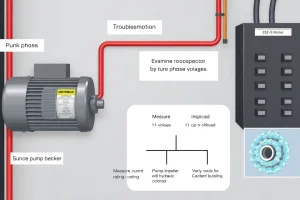
| Voltage imbalance across phases | Measure voltage phase-to-phase with a multimeter; imbalance above roughly 1–2% between phases warrants investigation, as motor heating from voltage imbalance increases disproportionately (roughly with the square of the imbalance percentage) |
| Single-phasing (one phase lost, typically from a blown fuse or failed contactor pole) | Measure current on all three phases—a missing phase shows zero current on that leg while the remaining two draw excessive current attempting to compensate |
| Poor ventilation / blocked cooling fan | Inspect motor cooling fins and fan shroud for debris; verify adequate clearance and airflow around the motor |
| High ambient temperature | Compare actual ambient at the motor location against its rated ambient (commonly 40°C / 104°F for standard motors); derate or use a higher-temperature-rated motor if ambient regularly exceeds this |
| Runout overload | Compare actual measured current against nameplate FLA; a motor drawing sustained current above nameplate (especially if the pump is operating at high flow / low head, near the runout end of its curve) is being asked to deliver more power than it was sized for |
| VFD-related heating (harmonics, switching losses) | Verify the motor is rated as “inverter-duty” if operated from a VFD, particularly on long cable runs; see the Motors & Energy pillar for compatibility guidance |
Motor Tripping the Breaker
Trips Immediately on Start
- Locked rotor / mechanical bind. With power safely locked out, attempt to manually rotate the shaft by hand (using the coupling or a strap wrench, never by hand on an exposed shaft near sharp edges). If it will not turn or turns with excessive resistance, suspect a seized bearing, a jammed impeller (foreign object, corrosion product, or scale buildup), or a broken/bound coupling.
- Ground fault. Insulation breakdown in the motor windings allows current to leak to ground, tripping a ground-fault protective device almost instantly. This typically requires motor testing (megohmmeter insulation resistance test) to confirm and generally means motor repair or replacement.
- Severe voltage imbalance or a missing phase at the source, present even before the motor starts drawing load.
Trips After Running for a While
- Sustained overload — current draw above the nameplate FLA for an extended period, most commonly from a runout operating condition (see the Motor Overheating table above) or from an increasingly worn pump requiring more power to do the same hydraulic work.
- Voltage imbalance developing under load (sometimes different from a no-load check) — recheck phase voltages with the motor actually running.
- Incorrectly set overload relay — if the thermal overload or electronic relay is set below the motor’s actual nameplate FLA and service factor allowance, it will trip on perfectly normal current draw. This is a common “nuisance trip” cause after a motor replacement where the new nameplate FLA differs from the old one and the relay setting was not updated.
- Ambient temperature at the motor control center (MCC) or breaker panel, if unusually high, can cause thermal-type protective devices to trip at a lower actual motor current than their rated setting would suggest, since many thermal trip mechanisms are themselves temperature-sensitive to their surrounding environment, not just to the current they’re sensing.
Short Cycling
Short cycling—the pump starting and stopping much more frequently than it should—is most common in pressure-tank and float-switch controlled systems (residential well systems, sump pumps, small booster systems) rather than continuously running process pumps.
Common Causes
- Waterlogged pressure tank — if the tank’s air cushion (or bladder, in a bladder-type tank) has been lost, the tank can no longer smooth out demand, and the pump cycles on and off rapidly with even small draws. This is the most common cause of short cycling in residential well and booster systems.
- Pressure switch cut-in/cut-out spread too narrow — a switch set to start the pump at, say, 38 psi and stop it at 40 psi provides very little buffer, causing frequent cycling under normal household demand. A wider spread (a common example being roughly 20 psi cut-in to 40 psi cut-out) allows the tank to absorb more draw between cycles.
- Check valve or foot valve failure — if the valve does not hold pressure when the pump stops, pressure bleeds down quickly and the pump restarts almost immediately.
- Pump oversized relative to the tank and typical draw — an oversized pump satisfies demand so quickly that even a properly charged tank cycles more often than an appropriately sized pump would.
- A leak somewhere in the system — even a small continuous leak (a running toilet, a dripping outdoor spigot, an underground line leak) can cause a well or booster system to cycle repeatedly trying to maintain pressure against continuous demand.
Why It Matters
Frequent cycling accelerates wear on the motor starting components, the pressure switch contacts, and the pump’s bearings and seals (which see repeated start-up transients rather than smooth continuous operation). It is worth fixing even when the system is “still working,” because the accumulated wear from short cycling shortens the service life of nearly every component in the system.
Related Failure Modes: Seals, Bearings, and Impellers
Three component-level failure modes deserve their own dedicated diagnostic articles, linked here with a brief summary:
Mechanical Seal Failure
Common root causes include running the pump dry (even briefly), piping-strain-induced seal face distortion (see the Piping Strain guidance), an incorrect flush plan for the application, abrasive solids reaching the seal faces, thermal shock, and elastomer incompatibility with the process fluid chemistry. See Mechanical Seal Failure: Root Causes and How to Diagnose Them for the full diagnostic guide.
Impeller Wear, Erosion, and Corrosion
The pattern of damage is diagnostically significant: cavitation damage typically appears as fine, localized pitting on the vane surfaces just downstream of where vapor bubbles collapse, while erosion from solids or high-velocity flow tends to produce a more generalized, sweeping wear pattern following the flow path. Corrosion damage (chemical attack rather than mechanical) often shows a different, non-directional surface texture. See Impeller Wear, Erosion, and Corrosion: Reading the Damage Pattern for photographs and pattern identification guidance.
Premature Bearing Failure
Beyond the lubrication causes covered in the Installation & Maintenance pillar, bearing failure can also result from electrical discharge damage (stray shaft currents, particularly relevant on VFD-driven motors without proper shaft grounding), excessive belt tension on belt-driven pumps, or contamination introduced during a previous repair. See Premature Bearing Failure in Pumps: Why It Happens and How to Stop It for the complete root-cause list.
Diagnostic Walkthroughs
Walkthrough 1: “The Pump Runs But Barely Any Water Comes Out”
A homeowner reports that a well pump runs continuously but delivers only a trickle at the faucet.
- Check rotation direction — the pump is a submersible, three-phase unit, and rotation cannot be visually confirmed. However, a submersible running backward often produces a noticeably reduced flow along with elevated running amps and reduced discharge pressure, which matches the complaint. This is checked by swapping any two of the three power leads at the surface splice or control panel (with power locked out) and observing whether pressure/flow improves. Result: pressure and flow improved substantially, confirming reversed rotation was the cause — most likely introduced during a recent electrical panel replacement.
Walkthrough 2: “New Rattling Noise, Started Last Week, No Other Symptoms”
A commercial building’s HVAC circulation pump develops a new rattling noise.
- NPSH check — the system hasn’t changed (same pump, same piping, same fluid temperature), so a genuine NPSH deficit is unlikely to have suddenly appeared. This points away from classic cavitation.
- Check the expansion tank and system fill/makeup water — closed hydronic loops rely on an expansion tank to accommodate thermal expansion; if the tank’s air charge has been lost or the system has developed a small air leak (a common occurrence at a recently serviced air vent or a newly added zone valve), air can be drawn into the circulation loop. Result: the automatic air vent at the system’s high point was found stuck partially open following recent zone valve maintenance, continuously drawing in a small amount of air. Repairing the vent eliminated the noise—confirming air entrainment rather than cavitation, consistent with the “no change in NPSH-relevant parameters” starting observation.
Walkthrough 3: “Motor Trips Randomly, Sometimes After an Hour, Sometimes After a Day”
An industrial process pump’s motor trips intermittently with no obvious pattern.
- Check nameplate FLA against actual measured current at various points during normal operation — current is within nameplate rating during most conditions.
- Check voltage balance across phases — a persistent 4% imbalance is found between two phases, which is enough to meaningfully increase motor heating over time (heating from voltage imbalance scales disproportionately, roughly with the square of the percentage imbalance) without necessarily showing up as an obvious overcurrent trip in a quick spot check.
- Trace the imbalance upstream — found to originate from an unevenly loaded distribution panel feeding several other pieces of equipment on the same service. Result: rebalancing the panel loads corrected the voltage imbalance and eliminated the intermittent trips, which had been intermittent precisely because the imbalance itself varied with the other equipment’s duty cycle throughout the day.
Common Troubleshooting Mistakes
Mistake 1: Disassembling Before Checking the Cheap Things
Pulling a pump apart before confirming valve positions, rotation direction, and prime status wastes labor and introduces new opportunities for installation error (gaskets, alignment, seal handling) on a pump that may not have needed to be opened at all.
Mistake 2: Assuming Noise Is Always Cavitation
As covered above, air entrainment produces very similar noise to cavitation but has an entirely different cause and fix. Run the NPSH calculation before assuming the more invasive (and often more expensive to correct) cavitation diagnosis.
Mistake 3: Treating a Single Vibration Reading in Isolation
A single “in spec” vibration reading tells you less than a trend. Establish a baseline at commissioning and track readings over time—a rapidly rising trend is actionable long before an absolute threshold is crossed.
Mistake 4: Replacing the Overload Relay Setting Without Checking Why It Tripped
A nuisance trip is sometimes correctly resolved by adjusting an incorrectly set overload relay—but only after confirming the motor’s actual current draw is genuinely within its safe operating range. Simply raising the trip setting to stop the tripping, without checking whether the underlying current draw is actually excessive, risks allowing real overload damage to go unprotected.
Mistake 5: Ignoring Short Cycling Because “It Still Works”
Short cycling is often dismissed because the system technically still delivers water or maintains pressure. The accumulated wear from excessive starts shortens component life across the board and is worth correcting even when there’s no acute failure yet.
Related Calculations and Further Reading
Recommended Calculators on PumpCalcs.com
- Cavitation Risk / NPSH Margin Checker — Quickly verify whether NPSH margin is adequate before assuming cavitation.
- Pump Diagnostic Decision Tree — An interactive, filterable version of the master symptom table above—answer a few questions about the symptom and get a ranked list of likely causes.
- Pump Curve Deviation Checker — Compare actual measured flow/head against the published pump curve to quantify how far performance has drifted from design.
- NPSH Available Calculator — Full NPSH calculation with altitude and temperature lookups.
Engineering Standards and References
- ANSI/HI 9.6.4: Rotodynamic Pumps for Vibration Measurements and Allowable Values — the vibration-diagnosis frequency guidance referenced above draws on the same measurement framework.
- NEMA MG1: Motors and Generators — reference for motor electrical fault conditions, service factor, and thermal protection.
- API 682: Pumps—Shaft Sealing Systems for Centrifugal and Rotary Pumps — for seal failure diagnosis and flush plan selection.
- Cameron Hydraulic Data (Flowserve) and Menon, E. Shashi, Working Guide to Pump and Pumping Stations — general engineering references for cavitation, NPSH, and system diagnostic principles used throughout this pillar.
Verification and Disclaimer
Content verification: Diagnostic guidance in this article reflects widely published pump maintenance and reliability engineering practice, cross-checked against ANSI/HI vibration standards, NEMA MG1 motor guidance, and standard hydraulic references. Failure-mode frequencies described as “most common” reflect general industry experience rather than a formal statistical study of any specific fleet of equipment—your own equipment’s actual failure history may differ.
Recommended use: This article provides a diagnostic starting framework for educational and preliminary troubleshooting purposes. Any electrical testing beyond basic voltage/current measurement should be performed by a qualified electrician; any internal pump inspection or repair should follow the specific manufacturer’s service instructions. For critical, hazardous, or high-value equipment, involve a qualified pump technician or engineer rather than relying solely on this guide.
Last updated: July 2026 | Reviewed by: [PE Reviewer Name, [State] PE License [Number]] | Reading time: ~19 minutes
FAQ
What is the most reliable early indicator of a developing pump blockage?
A gradual increase in suction pressure combined with a subtle rise in motor current, even before flow rate drops noticeably.
How often should pump seals be inspected for signs of overheating?
Inspect seals during every scheduled maintenance shutdown and after any event where motor temperature exceeds 85 °C for more than 30 minutes.
Can a pump operate safely at 80 % of its rated flow?
Yes, but efficiency will drop and the pump may run off‑design, increasing vibration and temperature. Adjust speed with a VFD if lower flow is expected regularly.
Is it acceptable to replace only the impeller when low flow is detected?
Only if the impeller is the confirmed cause (e.g., wear or blockage). Otherwise, verify suction line, clearance, and bearing condition before part replacement.
What safety precautions are essential when using an infrared camera on a hot pump?
Wear heat‑resistant gloves, maintain a safe distance (minimum 1 m), ensure the pump is de‑energized if the camera requires close proximity, and follow lock‑out/tag‑out procedures.
Leave a Reply