

Short Answer
Key Formula / Key Facts Box
Primary sizing equation (total dynamic head, TDH):
TDH = Hstatic + Hfriction
| Symbol | Meaning | US Unit | SI Unit | Plain‑English Restatement |
|---|---|---|---|---|
| TDH | Total Dynamic Head | ft | m | Overall head the pump must overcome. |
| Hstatic | Static lift (elevation difference) | ft | m | Vertical distance from sump water level to discharge point. |
| Hfriction | Friction loss in pipe | ft | m | Head lost due to pipe length, diameter, and flow. |
| Q | Flow rate | gpm | L/s | Volume of water moved per minute. |
| D | Pipe inner diameter | in | mm | Size of the discharge pipe. |
| L | Pipe length (run) | ft | m | Length of pipe from pump to outlet. |
Friction loss can be approximated with the Darcy‑Weisbach or Hazen‑Williams formulas; for typical residential sump pumps Hazen‑Williams is most convenient.
Overview — What It Is and Why It Matters
Sump pumps are low‑head centrifugal devices that protect basements and process pits by removing accumulating water. Proper sizing guarantees that the pump can lift the water from the deepest point of the pit to the discharge location without over‑working the motor, while also preventing the pump from turning on and off too frequently (short‑cycling). Undersized pumps may fail during a storm, leading to flooding, whereas oversized units waste energy and can cause cavitation, premature wear, and nuisance cycling.
The Method — Derivation and Variants
The governing relationship originates from energy conservation for incompressible flow:
ΔP/γ = Hstatic + Hfriction + Hminor
where ΔP is the pressure increase produced by the pump and γ is the specific weight of water (62.4 lb/ft³ US, 9.81 kN/m³ SI). In most residential sump applications minor losses (elbows, fittings) are lumped into the friction term.
Two common empirical forms for Hfriction are:
- Hazen‑Williams (US): Hf = 4.52 × Q1.85 × C‑1.85 × L ÷ D4.87 (ft) where C≈130 for new PVC.
- Darcy‑Weisbach (SI): Hf = f × (L/D) × (V²/2g) (m) with f obtained from the Moody chart.
Both equations express the same physics; the Hazen‑Williams version is a shortcut for water at 60 °F (15.6 °C) and smooth pipe. When temperature deviates or non‑water liquids are involved, the Darcy‑Weisbach approach must be used.
Worked Example
Example 1 – United States customary units
Scenario: A basement sump pit is 6 ft deep. The discharge pipe is 2 in (0.167 ft) PVC, 15 ft long, and runs to a floor‑drain 1 ft above the pit floor. Desired flow is 40 gpm. Use Hazen‑Williams with C = 130.
- Static lift: Hstatic = 6 ft (depth) – 0 ft (pump inlet at pit bottom) + 1 ft (exit height) = 7 ft.
- Convert flow to ft³/s: Q = 40 gpm ÷ 7.48 = 5.35 ft³/min = 0.089 ft³/s.
- Compute velocity: V = Q / A, A = π × (0.167/2)² = 0.0219 ft² → V = 0.089 / 0.0219 = 4.07 ft/s.
- Apply Hazen‑Williams: Hf = 4.52 × (40)1.85 × 130‑1.85 × 15 ÷ 24.87 ≈ 2.3 ft.
- TDH = 7 ft + 2.3 ft ≈ 9.3 ft.
- Choose a pump rated ≥ 10 ft TDH at 40 gpm; a typical 1‑½ hp sub‑mersible meets the requirement.
Example 2 – SI units
Scenario: A process pit in a plant is 1.8 m deep. A 50 mm (0.05 m) steel pipe, 4.5 m long, discharges to a level 0.3 m above the pit floor. Required flow is 150 L/min (0.15 m³/min = 0.0025 m³/s). Use Darcy‑Weisbach, f = 0.02 (smooth steel).
- Static lift: Hstatic = 1.8 m + 0.3 m = 2.1 m.
- Pipe area: A = π × (0.05/2)² = 1.96 × 10⁻³ m² → V = 0.0025 / 1.96e‑3 = 1.28 m/s.
- Friction loss: Hf = f × (L/D) × (V²/2g) = 0.02 × (4.5/0.05) × (1.28² / (2 × 9.81)) ≈ 0.58 m.
- TDH = 2.1 m + 0.58 m ≈ 2.68 m.
- A pump delivering 150 L/min at ≈ 3 m head (≈ 0.3 kW) satisfies the design.
Calculator
For quick verification, use an online total dynamic head calculator: http://pumpcalcs.com/calculators/total-dynamic-head/
Reference Values & Typical Ranges
- Typical residential sump pump flow: 30‑50 gpm (1.9‑3.2 L/s).
- Common TDH range: 8‑20 ft (2.5‑6 m) for basement applications.
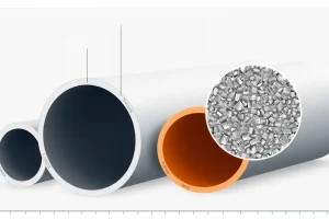
- Pipe diameter most often 1½‑2 in (38‑51 mm).
- Hazen‑Williams C‑value for new PVC: 130‑150; aged PVC: 110‑130.
- Motor horsepower selection: ½ hp for < 10 ft TDH, ¾‑1 hp for 10‑15 ft, 1‑½ hp for > 15 ft.
| Application | Flow (gpm / L s) | TDH (ft / m) | Typical Pump Size |
|---|---|---|---|
| Basement residential | 30‑45 gpm (1.9‑2.8 L/s) | 8‑12 ft (2.4‑3.7 m) | ½‑¾ hp sub‑mersible |
| Commercial utility pit | 60‑80 gpm (3.8‑5.0 L/s) | 12‑18 ft (3.7‑5.5 m) | 1‑1½ hp |
| Industrial process | 150‑300 L/min (0.15‑0.30 m³/min) | 3‑6 m | 1‑2 kW motor |
Application Guidance
When sizing a sump pump, follow these practical steps:
- Determine the maximum water level that can be tolerated (usually 1‑2 in below the pit lid).
- Measure the vertical distance from the lowest water level to the intended discharge point – this is the static lift.
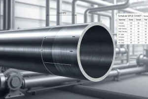
- Select pipe size that balances head loss and space constraints; larger diameters drastically reduce friction.
- Calculate friction loss using the appropriate formula; add a 10‑15 % safety margin for future pipe aging.
- Add any minor‑loss equivalents (elbows ≈ 0.5 ft each for 2‑in pipe).
- Choose a pump whose performance curve meets or exceeds the calculated TDH at the required flow. Verify that the NPSHavailable exceeds the pump’s NPSHrequired by at least 1 ft (0.3 m).
- Install a float switch with a hysteresis of 2‑3 ft to avoid short cycling; a check valve downstream prevents back‑flow that can cause re‑run.
Common Mistakes, Limits & Safety Notes
- Ignoring friction loss. Assuming TDH = static lift leads to undersized pumps and premature failure.
- Mixing US and SI units. Plugging a flow value in L/min into a Hazen‑Williams equation that expects gpm yields erroneous head.
- Using Hazen‑Williams for hot water or viscous fluids. The empirical C‑value is temperature‑specific; switch to Darcy‑Weisbach when temperature deviates > 20 °F (11 °C) from 60 °F.
- Undersizing the float switch travel. A short‑cycle switch can cause the motor to start every 30‑60 seconds, overheating the winding.
- Neglecting NPSH. Cavitation can erode impeller surfaces, especially when the pit is shallow and the suction lift is high.
- Installing the pump too high. A pump above the water level loses its priming head and may run dry.
- Forgetting a check valve. Back‑flow can raise the pit level and trigger rapid re‑starts.
- Over‑relying on manufacturer’s “maximum” rating. Continuous duty should be limited to 75‑80 % of the rated flow to extend life.
FAQ
How do I choose the correct pipe diameter for my sump pump?
Start with the manufacturer’s recommended minimum diameter, then use the Hazen‑Williams equation to see how much friction loss a smaller pipe adds. A 1½‑in pipe is typical for 30‑50 gpm; increasing to 2‑in reduces head loss by roughly 30 % and can keep the TDH within a smaller pump’s range.
Why does my sump pump turn on and off every minute?
The float switch is likely set too close to the water surface or the pit is too shallow, causing the water level to rise and fall quickly. Increase the switch travel (hysteresis) to 2‑3 ft or install a larger pit to give the pump enough time to drain before the switch re‑activates.
Can I use a standard residential pump for a commercial utility pit?
Commercial pits often require higher flow rates (60‑80 gpm) and greater TDH. A residential‑grade pump may not meet the required head or durability standards, leading to early failure. Select a pump rated for the commercial flow and head, and verify the NPSH margin.
What is the impact of pipe length on pump sizing?
Every foot of pipe adds friction loss, which increases TDH. Use the friction‑loss formula to calculate the contribution of length, then add a 10‑15 % safety factor for future pipe aging. In long runs, consider upsizing the pipe to keep head loss manageable.
Do I need a check valve on the discharge line?
Yes. A check valve prevents back‑flow when the pump stops, which can raise the pit water level and cause the float switch to re‑activate almost immediately, leading to short cycling and additional wear on the pump.
How can I verify that my pump has enough NPSH?
Calculate NPSH available: NPSHa = (static suction head + atmospheric pressure head + liquid vapor pressure head – friction loss in suction line). Compare it to the pump’s NPSH required (from the pump data sheet). A margin of at least 1 ft (0.3 m) is recommended.
Is it safe to install the pump above the water level?
No. Sub‑mersible pumps rely on being fully immersed to maintain cooling and suction head. Installing it above the water level can cause dry‑run damage, overheating, and rapid motor failure.
What maintenance practices reduce short cycling?
Regularly clean the pit and float switch, check that the discharge line is clear of obstructions, verify the check valve is functioning, and ensure the float switch travel is set correctly. Periodic inspection of the pump’s impeller for wear also helps maintain performance.

Leave a Reply