
Short Answer
Key Formula / Key Facts Box
| Fact | Description |
|---|---|
| Definition | The Best Efficiency Point (BEP) is the flow rate (QBEP) and head (HBEP) at which a pump converts mechanical shaft power into hydraulic power with the highest efficiency (ηmax). |
| Efficiency Formula | η = (ρ · g · Q · H) / (Pshaft) where ρ = fluid density, g = gravity, Q = volumetric flow rate, H = total head, Pshaft = input power. BEP is the point where η is maximum. |
| Preferred Operating Region (POR) | ANSI/HI 9.6.3 recommends operating between 70% and 120% of BEP flow for long-term reliability. For high-energy pumps, the range narrows to 80–110% of BEP. |
| Typical BEP Efficiency | Small centrifugal pumps: 40–60%; medium-size: 60–80%; large high-specific-speed pumps: 85–92%. |
| Key Consequence of Off-BEP Operation | Radial thrust increases exponentially as flow deviates from BEP, leading to shaft deflection, bearing overload, and seal failure. |
| Standards Reference | ANSI/HI 9.6.3-2012, ISO 9906:2012, and ISO 13709 (API 610) define BEP, preferred operating region, and allowable operating region. |
Overview — What It Is and Why It Matters
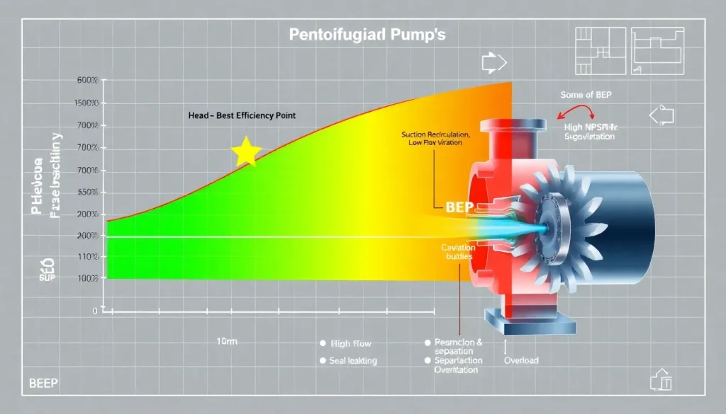
The Best Efficiency Point (BEP) is the hydraulic sweet spot of a centrifugal pump—the unique combination of flow rate and total developed head at which the pump’s internal hydraulic losses are minimized and its overall efficiency peaks. At BEP, the velocity triangles at the impeller inlet and outlet align most favorably with the volute or diffuser geometry, yielding smooth flow with minimal turbulence, recirculation, and separation. The pump’s shaft power is converted into fluid power with the least waste, and mechanical loads on the impeller, shaft, and bearings are balanced and predictable.
Operating away from BEP, whether at reduced flows (left of BEP) or excess flows (right of BEP), fundamentally alters the hydraulic force distribution inside the pump. At low flows, suction and discharge recirculation appear, causing intense pressure pulsations, cavitation, and increased radial thrust. At high flows, the impeller experiences higher axial and radial loads, and the net positive suction head required (NPSHr) rises sharply, often inducing classic cavitation. Both off-design conditions accelerate wear on wear rings, bearings, mechanical seals, and impeller vanes. Industry data show that pumps operated continuously outside the preferred operating region (POR)—typically 70–120% of BEP flow—experience a 2–5× increase in mean time between failures (MTBF). In high-energy pumps (above 300 kW per stage), the allowable operating region is even tighter, often 80–110% of BEP, to avoid catastrophic rotor-dynamic instability.
Understanding BEP is not merely an academic exercise; it is a critical selection and operational parameter. Specifying a pump that runs at or near its BEP under normal process conditions maximizes energy efficiency, reduces life-cycle costs, and minimizes unplanned downtime. Conversely, oversizing a pump (a common field mistake) forces it to operate left of BEP, leading to chronic vibration, seal leaks, and impeller erosion. Undersizing pushes the pump right of BEP, risking motor overload and severe cavitation damage. BEP therefore serves as the anchor point for all reliability-centered pump engineering.
The Method — Derivation and Variants
BEP is not derived from a single closed-form equation; it is identified from the pump’s performance curve, which is generated by testing the pump at constant speed across a range of flows. The overall efficiency η is calculated at each test point using the water horsepower (or hydraulic power) and measured shaft power:
US Customary Units:
Hydraulic Power (hp) = (Q [gpm] × H [ft] × SG) / 3960
Efficiency η = Hydraulic Power / Brake Horsepower (BHP)
SI Units:
Hydraulic Power (kW) = (Q [m³/s] × H [m] × ρ [kg/m³] × g [9.81 m/s²]) / 1000
Efficiency η = Hydraulic Power / Shaft Power (kW)
The constant 3960 in US units derives from: (8.34 lb/gal × 60 s/min) / (33,000 ft·lb/min per hp) = 3960, assuming water density. For other fluids, multiply by specific gravity. In SI, the formula is straightforward: ρgQH / 1000, with Q in m³/s, H in m, ρ in kg/m³, g = 9.81 m/s², and power in kW.
The BEP is the flow rate QBEP at which η reaches its maximum on the efficiency curve. Pump manufacturers provide this point on the performance curve, often marking it with a distinct symbol. For pumps tested with water, the BEP is typically stated at the impeller diameter and speed that yield the highest efficiency. When pumps handle viscous fluids, the BEP shifts to lower flows and heads, and the efficiency degrades; corrections are applied per ANSI/HI 9.6.7 or ISO/TR 17766.
Variants of the BEP concept include the preferred operating region (POR) and the allowable operating region (AOR). The POR is the flow range where the pump’s vibration is low and hydraulic performance is stable—commonly 70–120% of BEP flow. The AOR is the wider range within which the pump can operate without immediate mechanical damage, though long-term operation at the extremes is not recommended. For high-suction-energy pumps, the minimum continuous stable flow (MCSF) is often defined by the onset of suction recirculation, which may occur at 40–60% of BEP.
Worked Example
Example 1 (US Units): A centrifugal pump delivers 800 gpm of water at 150 ft total head. The brake horsepower measured at the shaft is 35 hp. Determine the efficiency and assess if the pump is near BEP if the manufacturer’s curve shows BEP at 800 gpm and 82% efficiency.
Hydraulic power = (800 × 150 × 1.0) / 3960 = 30.3 hp.
Efficiency = 30.3 / 35 = 0.866 → 86.6%.
The pump is operating at its BEP flow, but the measured efficiency is slightly higher than the catalog value, likely due to test tolerance. The pump is running optimally.
Example 2 (SI Units): A pump handles water (ρ = 1000 kg/m³) at 0.05 m³/s against 40 m head. Shaft power input is 22 kW. Find efficiency and compare with BEP efficiency of 78% at 0.05 m³/s.
Hydraulic power = (0.05 × 40 × 1000 × 9.81) / 1000 = 19.62 kW.
Efficiency = 19.62 / 22 = 0.892 → 89.2%.
The pump exceeds the catalog BEP efficiency, suggesting it is operating very close to its true BEP. If the flow were 0.03 m³/s (60% of BEP), hydraulic power would drop to 11.77 kW, and if shaft power were 18 kW, efficiency would be 65.4%, indicating off-BEP operation with increased radial loads.
Calculator
For quick determination of pump efficiency and hydraulic power, use the online pump efficiency calculator at http://pumpcalcs.com/calculators/pump-efficiency/. This tool accepts flow, head, specific gravity, and shaft power in both US and SI units and plots the operating point relative to a typical BEP range.
Reference Values & Typical Ranges
- Small end-suction pumps (<5 hp): BEP efficiency 40–55%, POR 70–120% of BEP flow.
- ANSI process pumps (5–200 hp): BEP efficiency 55–80%, POR 70–120% of BEP flow; AOR 50–125%.
- Large double-suction split-case pumps: BEP efficiency 85–92%, POR 80–110% of BEP flow; high-energy pumps require tighter control.
- API 610 refinery pumps: BEP efficiency 60–85%, preferred operating region 80–110% of BEP; minimum continuous stable flow typically 40–60% of BEP.
- Multistage pumps: BEP efficiency 75–88%, allowable operating region 60–120% of BEP, but axial thrust balance is sensitive to flow deviation.
- Viscous service: BEP shifts to ~90% of water BEP flow and efficiency drops by 5–20 points depending on viscosity; refer to ANSI/HI 9.6.7 correction charts.
Sources: ANSI/HI 9.6.3-2012, ISO 9906:2012, Lobanoff & Ross “Centrifugal Pumps: Design and Application,” and Hydraulic Institute standards.
Application Guidance
In real systems, the pump’s operating point is the intersection of the pump curve and the system curve. To maximize reliability, the system curve should intersect the pump curve within the POR at the normal design flow. When multiple pumps operate in parallel, each pump’s flow may deviate from BEP if the system curve is flat or if one pump is throttled. In such cases, a detailed analysis of individual pump BEP and combined operation is essential.
Field judgment often requires adjusting impeller diameter to shift the pump curve so that the duty point aligns with BEP. Trimming the impeller reduces both head and flow, moving the BEP to a lower flow rate. Variable-speed drives offer a more flexible solution: the affinity laws show that BEP flow scales linearly with speed, and BEP head scales with the square of speed, allowing the pump to maintain high efficiency across a range of conditions. However, even with VSDs, operation below 50% of BEP flow for extended periods is discouraged due to recirculation and low-frequency vibration.
When selecting a pump, always request the complete performance curve with efficiency, NPSHr, and power curves. Verify that the normal operating point lies between 80% and 110% of BEP flow, and that the maximum and minimum anticipated flows remain within the AOR. For critical services, specify vibration acceptance criteria per ISO 10816-7 and require a factory test at the specified operating point.
Common Mistakes, Limits & Safety Notes
- Oversizing the pump: Adding excessive safety margins to head and flow forces the pump to operate far left of BEP, causing chronic recirculation, vibration, and seal failures. Always base selection on accurate system head calculations, not rule-of-thumb overdesign.
- Ignoring the system curve: A pump selected at BEP may operate off-BEP if the actual system resistance differs from design. Field measurements of system head are essential during commissioning.
- Confusing BEP with duty point: The duty point is the required flow and head; the BEP is the pump’s optimum. A mismatch leads to inefficiency and damage. Always aim to match duty point to BEP, not the other way around.
- Operating at shutoff or very low flow: Even for short periods, dead-heading a centrifugal pump causes rapid temperature rise and potential catastrophic failure. Minimum flow bypass systems are mandatory for prolonged low-flow operation.
- Neglecting NPSH margin off-BEP: NPSHr increases at flows above BEP and also rises at very low flows due to recirculation. Ensure NPSHa exceeds NPSHr by at least 1–2 m across the entire operating range.
- Using BEP from water tests for viscous fluids without correction: Viscosity reduces efficiency and shifts BEP. Always apply HI or ISO viscosity correction factors.
- Assuming BEP is fixed: BEP changes with impeller trim, speed, and wear. Re-evaluate BEP after any modification or major overhaul.
- Ignoring radial thrust limits: Single-volute pumps experience high radial thrust away from BEP. For flows below 50% BEP, consider a double-volute or diffuser design to reduce shaft deflection.
- Safety consequence: Catastrophic bearing or seal failure due to off-BEP vibration can release hazardous fluids, causing environmental damage and personnel injury. Adhere to API 610 or ISO 13709 for critical services.
FAQ
What is the best efficiency point of a pump?
The Best Efficiency Point (BEP) is the flow rate and head at which a centrifugal pump operates with its highest hydraulic efficiency. At this point, internal losses are minimized, and the pump experiences the lowest vibration and radial thrust, making it the ideal operating condition for long-term reliability.
Why is operating away from BEP bad for a pump?
Operating away from BEP causes hydraulic instability, increased radial and axial loads, recirculation, and cavitation. These conditions accelerate wear on bearings, mechanical seals, and impellers, leading to premature failure, higher maintenance costs, and unplanned downtime.
How far from BEP can you operate a pump safely?
Industry standards recommend staying within the preferred operating region (POR), typically 70–120% of BEP flow for standard pumps. For high-energy pumps (above 300 kW per stage), the allowable range narrows to 80–110% of BEP. Short excursions outside this range are permissible but should be minimized.
What happens if a pump runs left of BEP?
Running left of BEP (low flow) causes suction and discharge recirculation, increased pressure pulsations, elevated radial thrust, and low-flow cavitation. This leads to shaft deflection, seal leakage, bearing overload, and impeller erosion, significantly reducing pump life.
What happens if a pump runs right of BEP?
Operating right of BEP (high flow) increases NPSH required, which can cause classic cavitation. It also raises axial and radial loads, may overload the motor, and accelerates wear ring and impeller vane erosion. Efficiency drops sharply, increasing energy consumption.
How do you find the BEP of a pump?
The BEP is identified from the manufacturer’s performance curve, where the efficiency curve peaks. It is usually marked with a special symbol. If the curve is not available, BEP can be approximated by testing the pump at several flows and calculating efficiency using hydraulic power and measured shaft power.
What is the preferred operating region of a pump?
The preferred operating region (POR) is the flow range around BEP where the pump operates with low vibration, stable hydraulics, and acceptable efficiency. ANSI/HI 9.6.3 defines POR as 70–120% of BEP flow for most pumps, and 80–110% for high-energy pumps.
Can you change the BEP of a pump?
Yes, BEP can be shifted by trimming the impeller (reduces BEP flow) or changing speed (BEP flow scales with speed). However, the pump’s hydraulic design sets the fundamental BEP location. Variable-speed drives allow the BEP to track a range of flows while maintaining high efficiency.
Does BEP change with speed?
According to affinity laws, BEP flow changes proportionally with speed, and BEP head changes with the square of speed. The efficiency at BEP remains nearly constant over a moderate speed range, but at very low speeds, efficiency may drop due to increased relative losses.
What is the difference between BEP and duty point?
The duty point is the flow and head required by the system. BEP is the pump’s optimum operating point. Ideally, the duty point should coincide with BEP. If they differ, the pump operates off-BEP, leading to reduced efficiency and potential damage.
Leave a Reply