
Short Answer
Key Formula / Key Facts Box
Governing equation for required total dynamic head (TDH):
H_{req}= frac{P_{desired}-P_{existing}}{rho,g}+ sum h_{fric}
In words: the pump must provide enough head to make up the pressure shortfall (converted to meters of water) plus all friction and fitting losses in the piping.
| Symbol | Meaning | US Unit | SI Unit |
|---|---|---|---|
| H_{req} | Required total dynamic head | ft | m |
| P_{desired} | Target downstream pressure | psi | kPa |
| P_{existing} | Measured upstream pressure | psi | kPa |
| rho | Water density | 62.4 lb/ft³ | 998 kg/m³ |
| g | Acceleration due to gravity | 32.174 ft/s² | 9.81 m/s² |
| sum h_{fric} | Total friction and fitting loss | ft | m |
Overview — What It Is and Why It Matters
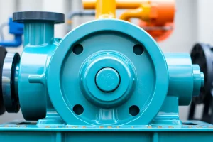
A booster pump is a compact centrifugal or positive‑displacement unit installed in a residential water distribution system to raise the pressure from the municipal supply (or a private well) to a level that guarantees adequate flow at every fixture. Insufficient pressure results in weak showers, sluggish dishwasher cycles, and reduced fire‑suppression capability, while an oversized pump wastes electricity, can cause pipe vibration, and may lead to cavitation that shortens service life.
From an engineering perspective, sizing a booster pump is a classic hydraulic design problem: determine the total dynamic head (TDH) the pump must overcome and the simultaneous flow rate the household will demand. The calculated operating point is then plotted on the manufacturer’s pump curve to verify that a suitable margin for head, efficiency, and NPSH exists.
The Method — Derivation and Variants
Applying Bernoulli’s equation between the inlet of the booster (point 1) and the most remote fixture (point 2) and neglecting minor elevation differences in a single‑story house gives:
frac{P_2}{rho g}=frac{P_1}{rho g}+sum h_{fric}+H_{pump}
Rearranging yields the required pump head:
H_{pump}=frac{P_2-P_1}{rho g}+sum h_{fric}
Two practical variants are used in the field:
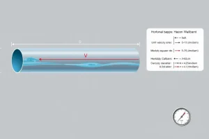
- US‑customary form: Convert the pressure difference (psi) to head (ft) with 1 psi ≈ 2.31 ft of water at 4 °C. Friction loss is obtained from Hazen‑Williams tables or the Darcy‑Weisbach equation expressed in ft.
- SI form: Use ΔP (kPa) ÷ (ρ·g) to obtain head in meters. Friction loss is calculated with the Darcy‑Weisbach equation: (h_f = ffrac{L}{D}frac{V^2}{2g}).
The constants differ only in unit conversion; the physics is identical. For most residential applications the Hazen‑Williams method is acceptable because water temperature is moderate and required accuracy is within 5 %.
Worked Example
Example 1 – US Units
A two‑story house measures 30 psi at the point where a booster will be installed. The homeowner desires at least 55 psi at the farthest fixture (a second‑floor shower). The longest pipe run is 80 ft of ½‑in. copper, containing three 90° elbows and one gate valve. Expected peak flow is 12 GPM.
- Pressure boost required: ΔP = 55 psi – 30 psi = 25 psi.
- Convert to head: H_{pressure}=25 psi × 2.31 ft/psi = 57.8 ft.
- Friction loss (Hazen‑Williams, C≈130 for new copper):
- Head loss per 100 ft at 12 GPM ≈ 9 ft.
- Pipe loss = (80 ft / 100 ft) × 9 ft = 7.2 ft.
- Fittings loss: each 90° elbow ≈ 0.5 ft, valve ≈ 1 ft → Σh_{fittings}=0.5×3 + 1 = 2.5 ft.
- Total friction = 7.2 ft + 2.5 ft = 9.7 ft.
- Required TDH = 57.8 ft + 9.7 ft ≈ 67.5 ft.
- Select a pump whose curve provides ≥12 GPM at ~70 ft head and includes at least a 10 % NPSH margin.
Example 2 – SI Units
Same house expressed metrically: Desired pressure = 380 kPa, existing = 207 kPa, ΔP = 173 kPa.
- Head from pressure: H_{pressure}=ΔP/(ρ·g)=173 kPa / (998 kg/m³·9.81 m/s²) ≈ 17.6 m.
- Friction loss (Darcy‑Weisbach): assume f = 0.02, L = 24 m, D = 0.0127 m, V = 0.76 m/s.
h_f = 0.02·(24/0.0127)·(0.76²/(2·9.81)) ≈ 2.3 m. - Fittings loss (equivalent length): 3 elbows (0.3 m each) + valve (0.5 m) = 1.4 m.
- Total friction = 2.3 m + 1.4 m = 3.7 m.
- Required TDH = 17.6 m + 3.7 m ≈ 21.3 m.
- Choose a pump delivering 45 L/min (≈12 GPM) at ≥22 m head with efficiency ≥65 %.
Calculator
For quick verification, use an online total dynamic head calculator: http://pumpcalcs.com/calculators/total-dynamic-head/
Reference Values & Typical Ranges
- Desired residential pressure: 40‑60 psi (≈2.8‑4.1 bar).
- Typical peak flow for a 4‑person household: 8‑15 GPM (30‑55 L/min).
- Booster pump head range: 30‑100 ft (9‑30 m) for most single‑family homes.
- Motor size: ½‑2 HP (0.4‑1.5 kW) for standard applications.
- Efficiency at best‑efficiency point (BEP): 60‑80 %.
- Minimum NPSH margin: 1 m (3 ft) for water at 50 °F (10 °C).
Sources: Hydraulic Institute Standard HI 9.6.3‑2020; ANSI/ISO 9906‑2018; Karassik et al., Pump Handbook, 4th ed.
Application Guidance
- Plot the calculated operating point (flow vs. head) on the pump manufacturer’s performance curves.
- Choose a pump whose curve intersects the point slightly to the left (higher head) to provide a 5‑10 % safety margin.
- Verify that the pump’s required NPSH (NPSHr) is lower than the available NPSH, which equals static suction head minus suction‑line friction loss.
- Confirm that the motor’s rated horsepower exceeds the hydraulic power divided by pump efficiency (P_h = ρgQH/η).
- Consider a variable‑frequency drive (VFD) for homes with fluctuating demand; a VFD can trim flow without changing the pump.
- Field adjustments: if measured downstream pressure is 5‑10 psi low, a small trim valve or a slightly larger pump can be used rather than a full redesign.
Common Mistakes, Limits & Safety Notes
- Mixing units. Forgetting the 2.31 ft/psi conversion under‑sizes the head by roughly a factor of two.
- Ignoring suction‑line friction. An undersized suction pipe can raise NPSHr above available NPSH, causing cavitation.
- Selecting a pump exactly at the curve point. Real‑world variations (temperature, wear) require a margin; operating at the BEP without head reserve accelerates wear.
- Over‑estimating flow. Using the sum of all fixture ratings instead of realistic concurrent flow (≈60‑70 % of total) leads to oversized equipment.
- Neglecting temperature effects. Hot‑water loops (≈60 °C) reduce density, slightly increasing required head; a 5 % increase is recommended by standards.
- Skipping electrical compliance. A pump that meets hydraulic specs but exceeds the branch‑circuit breaker rating creates fire hazards.
- Exceeding maximum allowable pressure. Municipal mains can surge; install a pressure‑reducing valve upstream of the booster to protect the pump.
FAQ
What is the minimum pressure a residential booster pump should deliver?
Most codes require at least 40 psi (2.8 bar) at fixtures to ensure adequate flow for showers and appliances; many homeowners aim for 55–60 psi for comfort.
Can I use a single‑stage pump for a two‑story house?
Yes, a properly sized single‑stage centrifugal pump is common for two‑story homes, provided the calculated TDH does not exceed the pump’s rated head.
How do I account for future fixture additions when sizing?
Add a 10‑15 % flow margin to the peak demand estimate and verify that the selected pump still meets the head requirement with the larger flow.
Do I need a pressure‑reducing valve before the booster?
A PRV protects the pump from upstream surges and reduces the suction head, helping to keep NPSHr within safe limits, especially in high‑rise installations.
Is a variable‑frequency drive (VFD) worth the cost?
A VFD allows the pump to modulate speed with demand, improving energy efficiency by up to 30 % and reducing wear caused by frequent on/off cycling.
What causes cavitation in a booster pump?
Cavitation occurs when the local pressure at the impeller inlet falls below the vapor pressure of water, often due to excessive suction‑line friction, low NPSHa, or operating the pump too close to its shut‑off head.
How often should I re‑check the pump’s performance?
Inspect pressure readings and flow rates annually; replace worn seals or adjust the VFD set‑point if pressure drops more than 5 psi from the design value.
Can I install the booster pump on the cold‑water line only?
Yes, most residential boosters are placed on the cold‑water supply; the hot‑water loop can be fed downstream, ensuring the pump does not handle temperature‑related density changes.


Leave a Reply