
Short Answer
Key Formula / Key Facts Box
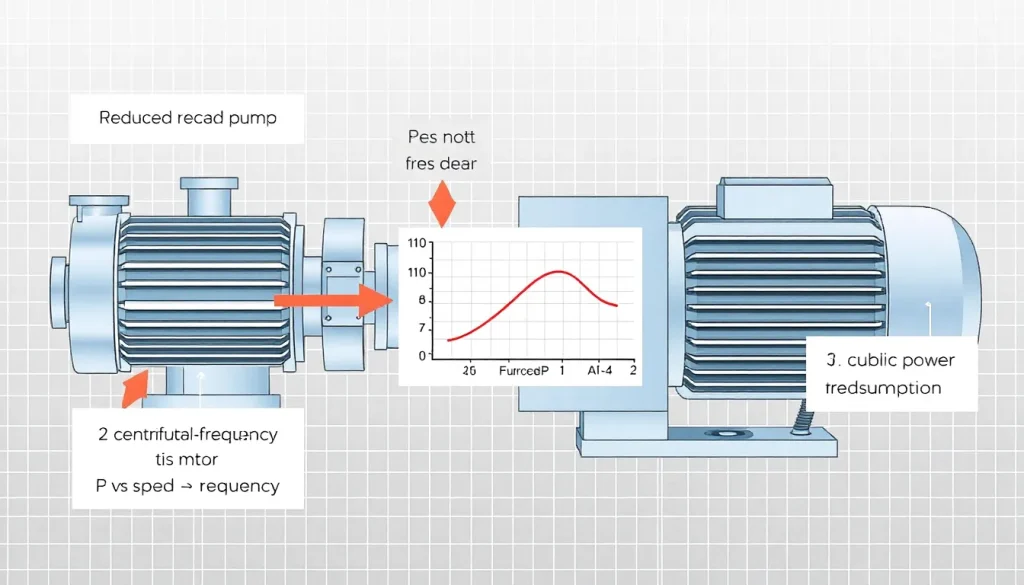
Primary Power‑Reduction Formula (Affinity Law)
P_actual = P_rated * (N/N_rated)^3
where:
| Symbol | Meaning | US Unit | SI Unit |
|---|---|---|---|
| P_actual | Motor electrical power at reduced speed | kW or hp | kW |
| P_rated | Motor power at name‑plate speed | kW or hp | kW |
| N | Actual motor speed | rpm | rpm |
| N_rated | Name‑plate (full‑speed) motor speed | rpm | rpm |
Plain‑English: Reducing pump speed by 20% cuts its electricity use to about 51% of the original because power varies with the cube of speed.
Overview — What It Is and Why It Matters
Variable Frequency Drives (VFDs) are solid‑state converters that adjust the frequency of the voltage supplied to an AC motor, thereby controlling the motor’s rotational speed. In pump applications, speed control allows the pump to follow the system’s hydraulic demand rather than forcing a constant flow at a fixed speed. Because centrifugal pump power is proportional to the cube of speed (the third affinity law), even modest reductions in speed translate into large electricity savings.
From an engineering standpoint, matching pump output to process requirements reduces waste heat, prolongs motor life, and can lower the overall plant carbon footprint. Conversely, operating a pump at full speed when only a fraction of its capacity is needed wastes energy and may cause cavitation or excessive wear.
The Method — Derivation and Variants
The classic pump affinity laws stem from the similarity of flow patterns at different speeds:
- Q ∝ N (flow varies linearly with speed)
- H ∝ N² (head varies with the square of speed)
- P ∝ N³ (power varies with the cube of speed)
Starting from the hydraulic power equation:
P_h = ρ g Q H
and substituting Q = Q_rated (N/N_rated) and H = H_rated (N/N_rated)², we obtain:
P_h = ρ g Q_rated H_rated (N/N_rated)³
Dividing by the overall efficiency η (motor × pump) gives the electrical power formula used in the key box.
Two common variants are used in practice:
- Speed‑Only Variant – When the system curve is relatively flat, engineers use P_actual = P_rated·(N/N_rated)³ directly.
- Flow‑Based Variant – If the required flow Q_req is known, the needed speed is N = N_rated·(Q_req/Q_rated). Substituting back yields P_actual = P_rated·(Q_req/Q_rated)³.
US‑customary and SI forms are identical mathematically; only the unit symbols change (hp vs kW, ft·lb vs J, etc.). The constants ρ (density) and g (gravity) appear only when converting hydraulic power to electrical power.
Worked Example
Example 1 – US Units
A 150 hp centrifugal pump runs at 3,600 rpm on a 460 V, 3‑phase motor. The process requires only 70 % of the rated flow. What motor power is needed after installing a VFD?
- Determine speed ratio: N/N_rated = (Q_req/Q_rated) = 0.70.
- Apply cubic law: P_actual = 150 hp × (0.70)³ = 150 hp × 0.343 = 51.5 hp.
- Convert to kW (1 hp = 0.746 kW): 51.5 hp × 0.746 = 38.4 kW.
Result: The VFD reduces electrical demand from roughly 112 kW (150 hp) to about 38 kW – a 66 % savings.
Example 2 – SI Units
A 110 kW, 1,800 rpm pump must deliver 60 % of its design flow. Calculate the new power draw.
- Speed ratio = 0.60.
- P_actual = 110 kW × (0.60)³ = 110 kW × 0.216 = 23.8 kW.
The VFD trims power consumption by 78 % compared with the full‑speed condition.
Calculator
For quick on‑line calculations, use the VFD pump power estimator at http://pumpcalcs.com/calculators/total-dynamic-head/.
Reference Values & Typical Ranges
- Typical motor efficiency (η_motor): 0.90 – 0.96 for premium‑efficiency IEC 60034‑30‑1 motors.
- Typical pump hydraulic efficiency (η_pump): 0.65 – 0.85 for clean‑water centrifugal pumps.
- Speed reduction limits: Most VFDs support 30 % – 100 % of name‑plate speed; below 30 % may cause torque pulsations.
- Energy saving potential: 20 % – 80 % depending on how far the operating point deviates from full speed.
- Annual electricity cost reduction: $0.07–$0.15 per kWh saved (U.S. average 2023).
Sources: IEC 60034‑30‑1, ASME B73.1, DOE Energy Saver Guide.
Application Guidance
When specifying a VFD for a pump, follow these steps:
- Identify the minimum and maximum flow rates required by the process.
- Convert flow limits to corresponding motor speeds using the linear affinity law (N = N_rated·Q/Q_rated).
- Select a VFD rated for the motor’s full‑load current at the highest speed and capable of the low‑speed torque (often 1.5–2× the motor’s rated torque).
- Program the VFD with a closed‑loop control (e.g., pressure transducer or flow sensor) to automatically adjust speed.
- Include harmonic filters or line reactors if the plant has sensitive instrumentation.
Field‑judgment adjustments include accounting for pump wear (reduced head) and system curve changes (valve fouling). Re‑evaluate the speed‑flow relationship annually.
Common Mistakes, Limits & Safety Notes
- Ignoring Motor Torque Curve – Selecting a VFD that cannot deliver the required torque at low speeds leads to stall and motor overheating.
- Unit Mix‑up – Using hp with kW or rpm with rad/s in the cubic formula produces wildly inaccurate results.
- Assuming Linear Power Reduction – Power follows a cubic relationship; a 10 % speed cut saves ≈ 27 % energy, not 10 %.
- Undersizing the VFD Rating – The VFD must be sized for the motor’s full‑load amps, not the reduced‑speed amps.
- Neglecting Harmonics – VFDs generate voltage harmonics that can affect variable‑frequency drives of other equipment; use line reactors if required.
- Bypassing Over‑Current Protection – Some installations disable motor overload relays; this violates NEC/IEC safety rules.
- Operating Below Minimum Speed – Below ~30 % of rated speed, many pumps experience cavitation and surge; consult the pump manufacturer.
FAQ
Can a VFD be retrofitted to an existing pump‑motor set?
Yes, provided the motor is compatible (e.g., not a shaded‑pole or split‑phase motor) and the VFD is sized for the motor’s full‑load current and low‑speed torque. Mechanical coupling and shaft alignment should also be checked.
What is the typical payback period for installing a VFD on a pump?
Payback usually ranges from 6 months to 3 years, depending on the pump’s duty cycle, the amount of speed reduction, electricity rates, and any incentives from utilities.
Do VFDs affect pump reliability?
When properly sized, VFDs improve reliability by reducing mechanical stress, eliminating start‑stop surges, and lowering cavitation risk. However, excessive low‑speed operation can lead to heat buildup and seal wear if not monitored.
How do I size a VFD for a 3‑phase motor?
Select a VFD rated for at least the motor’s full‑load amps (FLA) at rated voltage, and ensure its torque capability exceeds the motor’s rated torque at the lowest speed you intend to run.
Is harmonic distortion from VFDs a concern for my plant?
Yes, VFDs generate current harmonics that can affect sensitive equipment. Using line reactors, harmonic filters, or VFDs with built‑in active filtering mitigates the issue.
Can a VFD be used with a positive‑displacement pump?
Positive‑displacement pumps also benefit from speed control, but their power varies linearly with speed, not cubically. Energy savings are still realized, but the reduction factor is less dramatic than for centrifugal pumps.
What safety standards govern VFD installations?
In the U.S., NEC Article 430 and IEC 61800‑5‑1 cover protection, grounding, and overload settings. Always follow the manufacturer’s wiring diagram and include appropriate short‑circuit and over‑current devices.
Do I need a dedicated transformer for a VFD?
Most modern VFDs accept the same line voltage as the motor (e.g., 460 V). A transformer is only required if the motor voltage differs from the available supply or for isolation purposes.
Leave a Reply