
Short Answer
Key Formula / Key Facts Box
Fundamental Positive‑Displacement Pump Flow Equation
Q = N × Vd × etav
| Symbol | Meaning | US Unit | SI Unit |
|---|---|---|---|
| Q | Volumetric flow rate | gal·min-1 | m³·s-1 |
| N | Rotational speed | rev·min-1 (rpm) | rev·s-1 (rps) |
| Vd | Geometric displacement per revolution | in³·rev-1 | cm³·rev-1 |
| etav | Volumetric efficiency (actual ÷ theoretical) | – | – |
Plain‑English: each rotation delivers a fixed geometric volume, reduced by internal slip and leakage.
Overview — What It Is and Why It Matters
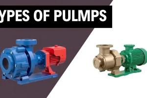
Gear, diaphragm, and peristaltic pumps belong to the positive‑displacement (PD) family, meaning a constant volume of fluid is transferred for every mechanical increment—one gear tooth, one diaphragm stroke, or one roller pass. Unlike centrifugal machines, PD pumps generate flow independent of downstream pressure up to the design limit, making them indispensable for metering, high‑viscosity, or shear‑sensitive fluids. Selecting the correct PD type prevents costly downtime, protects product integrity, and satisfies pressure‑rating regulations. Errors in sizing or material compatibility can cause excessive wear, leakage, or catastrophic failure, especially in hazardous or sterile environments.
The Method — Derivation and Variants
The base equation Q = N·Vd·ηv follows directly from the definition of displacement. For a gear pump, Vd is the inter‑tooth volume derived from gear geometry; for a diaphragm pump, Vd equals the swept chamber volume per stroke; for a peristaltic pump, Vd is the tube volume displaced by one roller pass.
In US‑customary units the equation is often written as:
Q (gal/min) = N (rpm) × Vd (in³/rev) × ηv ÷ 231
where 231 in³ = 1 gal. In SI units the equivalent form is:
Q (m³/s) = N (rev/s) × Vd (cm³/rev) × ηv ÷ 1,000,000
Typical volumetric efficiencies differ among families: gear pumps 85‑95 % (internal slip), diaphragm pumps 90‑98 % (well‑matched check valves), and peristaltic pumps 70‑90 % (tube compression losses). When motor power is required, the flow can be combined with pressure rise:
P (W) = (Q·Δp) / ηm
with Δp = ρ·g·(Hd‑Hs) and ηm the overall mechanical efficiency.
Worked Example
Example 1 – US Units (Gear Pump)
- Design requirement: 120 gal/min of mineral oil at 150 psi discharge.
- Chosen pump: 8‑lobe external‑gear unit, Vd = 0.45 in³/rev.
- Assume ηv = 0.90.
- Calculate required speed:
Q = N·Vd·ηv ÷ 231 → 120 = N·0.45·0.90 ÷ 231 → N = (120·231)/(0.45·0.90) ≈ 68,800 rpm.
Because 68,800 rpm exceeds typical gear‑pump limits, the designer must either select a larger‑displacement gear set (e.g., Vd = 1.2 in³/rev) or operate two pumps in parallel.
Example 2 – SI Units (Diaphragm Pump)
- Requirement: 0.015 m³/s of high‑viscosity silicone oil at 1.2 MPa.
- Chosen pump: double‑acting diaphragm with chamber volume Vd = 12 cm³ per stroke (one forward and one back stroke per revolution).
- Assume ηv = 0.96 and motor speed N = 150 rev/s (9,000 rpm).
Convert Vd to m³/rev: 12 cm³ = 12 × 10⁻⁶ m³ = 1.2 × 10⁻⁵ m³.
Q = N·Vd·ηv = 150 × 1.2 × 10⁻⁵ × 0.96 ≈ 0.00173 m³/s, far below the target.
To meet 0.015 m³/s, increase N to 1,300 rev/s (78,000 rpm) or use a larger chamber (Vd = 80 cm³). With N = 1,300 rev/s, Q ≈ 0.015 m³/s, satisfying the specification.
Calculator
For rapid sizing, use the online positive‑displacement pump flow calculator: http://pumpcalcs.com/calculators/total-dynamic-head/.
Reference Values & Typical Ranges
- Gear‑pump displacement per tooth: 0.02 – 0.30 in³ (0.33 – 4.9 cm³).
- Diaphragm chamber volume: 5 – 200 cm³ (0.3 – 12 in³) per stroke.
- Peristaltic tube ID: 0.5 – 10 mm (0.02 – 0.39 in).
- Volumetric efficiency: gear 85‑95 %; diaphragm 90‑98 %; peristaltic 70‑90 %.
- Maximum continuous pressure (standard materials): gear 250 psi (1.7 MPa), diaphragm 300 psi (2.1 MPa), peristaltic 150 psi (1.0 MPa).
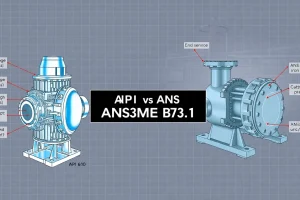
Sources: ASME B73.1‑2015, ISO 2858:2015, and C. K. McGowan, Positive‑Displacement Pump Design (2020).
Application Guidance
When choosing among the three families, weigh fluid properties, required accuracy, and maintenance considerations:
- Gear pumps excel with low‑ to moderate‑viscosity oils, provide high flow densities in compact packages, and tolerate moderate pressure spikes. Avoid abrasive slurries unless metal‑on‑metal gear sets are specified.
- Diaphragm pumps are the workhorse for chemically aggressive, high‑viscosity, or sanitary streams (food, pharma). Their hermetic separation eliminates leakage, but flow‑rate density is limited.
- Peristaltic pumps are unrivaled for shear‑sensitive fluids (cell cultures, polymer melts) because the fluid contacts only the tubing. They also enable quick sterile line changes, though tube wear mandates frequent replacement.
Field adjustments include derating speed by ~10 % for each 50 °F (28 °C) temperature rise and applying a safety factor of 1.25 to Vd when entrained gas is present.
Common Mistakes, Limits & Safety Notes
- Mixing US and SI units in the flow equation – always convert Vd to match Q’s unit system before calculation.
- Assuming ηv = 1.0. Real pumps lose volume to slip; using 100 % efficiency can lead to motor oversizing and cavitation.
- Neglecting suction‑head limitations. Positive‑displacement pumps can cavitate if Net Positive Suction Head Available (NPSHA) is lower than the pump’s NPSHR.
- Over‑speeding a gear pump beyond the manufacturer’s rating, which can cause gear‑tooth breakage and sudden leakage.
- Selecting incompatible tubing for peristaltic pumps (e.g., silicone with strong solvents) – tube degradation results in burst and loss of containment.
- For diaphragm pumps, failing to vent displaced air on the suction side, leading to pulsation, bearing overload, and premature wear.
- Ignoring the impact of fluid viscosity on ηv. High‑viscosity fluids increase slip and reduce effective flow.
- Skipping routine inspection of check‑valve seats in diaphragm pumps; worn seats cause back‑flow and pressure spikes.
FAQ
What is the main advantage of a peristaltic pump over a gear pump?
Peristaltic pumps isolate the fluid from moving parts, eliminating leakage and providing gentle, low‑shear handling—ideal for sterile or shear‑sensitive applications where gear pumps would cause contamination or product degradation.
Can a diaphragm pump handle abrasive slurries?
Standard diaphragm pumps are not suited for abrasive slurries because the flexible membrane can be punctured. Specialized reinforced elastomers or metal‑bellows designs can tolerate mild abrasion, but wear rates remain high.
How do I calculate the required motor power for a positive‑displacement pump?
First determine flow (Q) with Q = N·Vd·ηv. Then compute pressure rise Δp = ρ·g·(Hd‑Hs). Motor power follows P = (Q·Δp) / ηm, where ηm is overall mechanical efficiency.
Why does volumetric efficiency drop at high fluid viscosity?
Higher viscosity increases internal slip and leakage around gear teeth or diaphragm seals, reducing the fraction of theoretical displacement that appears as useful flow, thus lowering ηv.
What maintenance is critical for diaphragm pumps?
Regular inspection of check‑valve seats, ensuring the vent line is clear, and replacing worn diaphragms are essential. Failure to do so can cause back‑flow, pressure spikes, and excessive pulsation.
How often should peristaltic pump tubing be replaced?
Tubing life depends on fluid chemistry, temperature, and pump speed, but a typical replacement interval is 1,000‑3,000 hours of continuous operation or whenever visual inspection shows cracking, swelling, or loss of elasticity.
Leave a Reply