
Short Answer
Key Formula / Key Facts Box
| Symbol | Meaning | US Unit | SI Unit | Plain‑English Restatement |
|---|---|---|---|---|
| Q | Flow rate | gpm | m³/h | How much liquid the pump moves per unit time. |
| H | Head (energy per weight) | ft | m | Equivalent height the pump can raise the liquid. |
| P | Power | hp | kW | Electrical or mechanical power required. |
| N | Rotational speed | rpm | r/min | Speed of the pump impeller. |
| η | Overall efficiency | % | % | Ratio of hydraulic power to input power. |
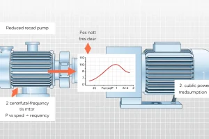
The pump affinity laws relate changes in speed (N) to flow (Q), head (H), and power (P):
Q₂ = Q₁·(N₂/N₁)
H₂ = H₁·(N₂/N₁)²
P₂ = P₁·(N₂/N₁)³
These equations assume the pump geometry remains unchanged and the fluid properties are constant.
Overview — What It Is and Why It Matters
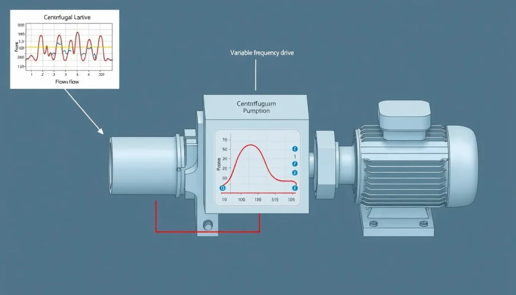
A variable‑frequency drive (VFD) varies motor speed to match pump output to process demand. While VFDs often lower energy use and reduce mechanical stress, they can be the wrong choice when the pump‑system interaction violates the assumptions behind the affinity laws or when ancillary equipment cannot tolerate speed changes. Selecting a VFD inappropriately can cause cavitation, excess wear, motor overheating, harmonic distortion, and even safety hazards.
Engineers must therefore evaluate not only the energy‑saving potential but also the hydraulic, mechanical, and control‑system constraints that may render a VFD unsuitable.
The Method — Derivation and Variants
The affinity laws stem from the similarity of dynamically scaled pump geometries. Starting with the Euler pump equation for head:
H = (U₂·V_{θ2} – U₁·V_{θ1})/g
where U = πDN/60 is the peripheral speed (D = impeller diameter). Holding D constant and scaling N yields the proportionalities shown in the Key Facts box. The three classic variants are:
- Speed‑control (VFD) variant: Apply the laws directly to predict Q, H, and P at any new speed.
- Impeller‑trim variant: Replace N with D (diameter) when the pump is physically trimmed instead of speed‑controlled.
- Viscosity‑correction variant: For non‑Newtonian or high‑viscosity fluids, introduce a correction factor (K_μ) that reduces the accuracy of the pure speed‑based laws.
When a VFD is considered, the speed‑control variant is used, but only if the system curve (system head vs. flow) remains smooth and the motor can handle the variable torque demand without oversizing.
Worked Example
Scenario A – US customary units
A 5‑hp centrifugal pump (N₁ = 3,600 rpm) delivers 1,200 gpm at 150 ft head. The process requires a reduced flow of 800 gpm while maintaining the same head. Determine the VFD speed and the new motor power.
- Calculate the speed ratio using the flow law: N₂/N₁ = Q₂/Q₁ = 800/1,200 = 0.667.
- New speed: N₂ = 0.667 × 3,600 ≈ 2,400 rpm.
- Head at new speed: H₂ = H₁·(N₂/N₁)² = 150 ft × (0.667)² ≈ 66.7 ft. Because the process demands the original 150 ft, a VFD alone cannot meet the requirement; a throttling valve or a different pump is needed.
- Assuming the head requirement is relaxed to 66.7 ft, compute power: P₂ = P₁·(N₂/N₁)³. First find hydraulic power at original condition: P_h1 = ρ·g·Q₁·H₁ / (3960) ≈ 5 hp (given). Then P₂ = 5 hp × (0.667)³ ≈ 1.5 hp.
- Motor rating: Select a motor ≥ 2 hp to provide a safety margin.
Scenario B – SI units
A 15 kW (≈ 20 hp) pump runs at 1,800 rpm, delivering 0.09 m³/s at 30 m head. The system requires 0.06 m³/s while keeping head constant.
- Speed ratio: N₂/N₁ = Q₂/Q₁ = 0.06/0.09 = 0.667.
- New speed: N₂ = 0.667 × 1,800 ≈ 1,200 rpm.
- Head at new speed: H₂ = 30 m × (0.667)² ≈ 13.3 m (again insufficient for the original head).
- Power: P₂ = 15 kW × (0.667)³ ≈ 4.5 kW.
- Select a motor rated ≥ 6 kW.
Both examples illustrate that a VFD can meet a lower flow demand only if the system head requirement also drops proportionally. When head must stay constant, the VFD is the wrong choice.
Calculator
Use an online affinity‑law calculator to verify speed, flow, head, and power relationships: http://pumpcalcs.com/calculators/total-dynamic-head/
Reference Values & Typical Ranges
- Motor overload factor for VFD operation: 1.15 – 1.25 (per IEEE 519).
- Maximum speed reduction without cavitation for most centrifugal pumps: 30 %–40 % of rated speed.
- Harmonic distortion limit for VFD‑fed motors (THD): <5 % (IEC 61800‑3‑2).
- Typical VFD efficiency range: 95 %–98 % at full load, dropping to 85 % – 90 % at 30 % load.
- Minimum pump net positive suction head (NPSH) margin for VFD operation: 2 ft (0.6 m) extra over the design NPSH.
Application Guidance
When evaluating a VFD, follow these steps:
- Map the system curve. Plot H versus Q for the piping, valves, and elevation. Identify the intersection with the pump’s characteristic curve.
- Check cavitation risk. Reduce speed only as far as the NPSH available stays above NPSH required plus the 2‑ft safety margin.
- Assess downstream equipment. Throttling valves, flow meters, and pressure relief devices often cannot tolerate large speed changes; they may need redesign.
- Size the motor for variable torque. Motor torque at low speed can exceed the rated torque at full speed; select a motor with a higher torque rating or use a VFD with a built‑in torque‑limiting function.
- Evaluate harmonic impact. VFDs generate non‑sinusoidal voltage; verify that cable sizing, grounding, and EMI shielding meet IEC 61800‑3‑2.
- Consider alternative controls. If the process demands a constant head, consider a throttling valve, a bypass line, or a variable‑area pump (e.g., vane or eccentric) instead of a VFD.
Common Mistakes, Limits & Safety Notes
- Assuming the affinity laws hold for highly viscous or multiphase fluids – they break down beyond 10 cP or > 30 % gas volume fraction.
- Reducing speed below the pump’s minimum stable speed (often 50 % of rated) and causing flow‑separation and severe vibration.
- Ignoring the motor’s VFD‑rated torque curve; oversizing the motor can lead to overheating because cooling is fan‑driven and proportional to speed.
- Mixing US and SI units in the affinity calculations – a common source of 10‑fold errors.
- Failing to provide a proper harmonic filter, resulting in premature bearing failure or interference with nearby instrumentation.
- Using a VFD to replace a pressure‑control valve in a closed‑loop system; the pump may hunt and cause pressure oscillations.
- Neglecting the impact on pump seals – lower speeds can cause oil‑cavitation in mechanical seals, reducing seal life.
- Over‑relying on VFD energy‑saving calculators without accounting for part‑load efficiency penalties.
FAQ
Can a VFD be used on a pump that operates continuously at full speed?
Yes, but the energy‑saving benefit disappears. The VFD may still provide soft‑start capability and motor protection, but the cost‑benefit analysis should consider the added capital and harmonic mitigation expenses.
What is the main cause of cavitation when a VFD reduces pump speed?
Reducing speed lowers the pump’s head, which can drop the suction pressure below the fluid’s vapor pressure, especially if the system’s NPSH margin is small. This creates vapor bubbles that collapse and damage impeller surfaces.
Do VFDs affect pump seal life?
Lower speeds can change the lubrication regime inside mechanical seals, sometimes leading to oil‑cavitation or dry‑running conditions. Seal manufacturers often recommend a minimum speed or a seal‑specific VFD programming to maintain proper cooling.
Is it safe to run a centrifugal pump at 20 % of its rated speed?
Generally not. Most centrifugal pumps are rated for a minimum of about 50 % of rated speed. Below that, flow becomes unstable, efficiency plummets, and vibration can increase dramatically.
How do I size a motor for a pump that will be driven by a VFD?
Select a motor whose torque curve exceeds the pump’s torque demand at the lowest expected speed, and include a 15 %–25 % overload factor per IEEE 519. Consider a motor with a higher NEMA‑design B rating for better start‑torque capability.
Can I replace a throttling valve with a VFD to control pressure?
Only if the system curve is relatively flat and the pump can maintain the required head at lower speeds without cavitation. In many high‑pressure, low‑flow systems, a valve provides finer control and avoids speed‑related pump issues.
What harmonic filtering is required for a 10 kW VFD feeding a pump motor?
Typically a passive L‑C filter sized to limit THD below 5 % at the motor terminals. The exact filter rating depends on the VFD’s switching frequency and the motor’s impedance; manufacturers often provide selection charts.
Why does part‑load efficiency sometimes drop more than expected with a VFD?
At low speeds the pump’s hydraulic efficiency falls because the impeller operates away from its design point, and the motor’s electrical losses increase due to higher slip and stray losses. This combined effect reduces overall system efficiency.
Leave a Reply