
Short Answer
Key Formula / Key Facts Box
| Symbol | Meaning | US Unit | SI Unit | Plain‑English Restatement |
|---|---|---|---|---|
| Q | Volumetric flow rate | gpm | m³/h | How much fluid moves per minute. |
| H | Total dynamic head | ft | m | Energy per weight the pump must add. |
| ΔP | Pressure rise across the pump | psi | kPa | Difference between outlet and inlet pressure. |
| N | Rotational speed | rpm | rev/min | How fast the impeller spins. |
| D | Impeller diameter | in | mm | Size of the rotating wheel. |
| η | Hydraulic efficiency | % | % | How well the pump converts input power to fluid energy. |
Fundamental affinity law (US & SI):
Q₁ / Q₂ = (N₁ / N₂)·(D₁ / D₂)
Overview — What It Is and Why It Matters
In many industrial and municipal systems, a pump is the heart that creates the required flow and pressure. When either flow (Q) or pressure (ΔP or head H) falls short of design values, the downstream process can stall, product quality can suffer, and energy consumption can rise dramatically. Understanding the root causes is essential for keeping plants running safely, maintaining warranty compliance, and avoiding costly downtime.
Low‑flow or low‑pressure symptoms are often confused with each other because the two variables are linked by the system curve. A drop in head reduces the driving force for flow, while a blockage that limits flow also reduces the pressure developed by the pump. The distinction matters because corrective actions differ: you may need to clean a suction line, replace a worn impeller, or simply re‑size the motor.
The Method — Derivation and Variants
The basic hydraulic relationship for a centrifugal pump is:
ΔP = ρ·g·H
where ρ is fluid density and g is gravitational acceleration. Combining this with the pump affinity laws gives the most useful design equation for troubleshooting:
Q₁ = Q₂·(N₁/N₂)·(D₁/D₂)
and
H₁ = H₂·(N₁/N₂)²·(D₁/D₂)²
These equations are derived from the similarity of rotating machinery. The constants disappear because the impeller geometry is assumed unchanged. In US‑customary form, the head is expressed in feet and the pressure rise in psi (1 ft H₂O ≈ 0.433 psi). In SI, head is in metres and pressure in kilopascals (1 m H₂O ≈ 9.81 kPa).
When the pump operates away from its best‑efficiency point (BEP), the actual Q–H curve deviates from the ideal square‑root shape. In such cases, manufacturers provide performance curves that must be interpolated. The affinity laws remain valid for small adjustments (±10 % speed or diameter).
Worked Example
Example 1 – US Units
A 10‑in. diameter centrifugal pump runs at 1,800 rpm delivering 1,200 gpm at 150 ft of head. The system is upgraded, and the impeller is replaced with a 12‑in. version that will operate at 1,650 rpm. What flow can be expected if the head requirement stays at 150 ft?
- Calculate the speed ratio: N₁/N₂ = 1,650 / 1,800 = 0.917.
- Calculate the diameter ratio: D₁/D₂ = 12 / 10 = 1.20.
- Apply the flow affinity law: Q₁ = 1,200 gpm × 0.917 × 1.20 ≈ 1,322 gpm.
- Since head is unchanged, the pump will operate near the same point on its curve; efficiency may drop slightly.
Example 2 – SI Units
A 0.25 m impeller pump at 1,500 rpm produces 0.08 m³/s at 30 m head. After a valve restriction, the measured flow drops to 0.045 m³/s. Estimate the new head assuming the pump speed is unchanged.
- Use the head affinity law (inverse of flow law for constant speed): H₁/H₂ = (Q₁/Q₂)².
- Rearrange: H₂ = H₁·(Q₂/Q₁)² = 30 m × (0.045/0.08)² ≈ 30 m × (0.5625)² ≈ 30 m × 0.316 ≈ 9.5 m.
- The head has fallen by roughly 68 % – a classic sign of severe throttling or cavitation.
Calculator
For quick calculations of total dynamic head, flow, or speed changes, use the online tool: Pump Total Dynamic Head Calculator.
Reference Values & Typical Ranges
- Typical centrifugal pump efficiency: 60 %–85 % (ISO 9906).
- Acceptable NPSH margin: ≥ 1.5 m (5 ft) for most liquids.
- Pressure drop across a clean 2‑inch suction pipe at 200 gpm: ≈ 2 psi (0.14 bar).
- Cavitation inception pressure for water at 25 °C: ≈ −2.3 psi (‑16 kPa) relative to vapor pressure.
- Viscosity correction factor (K_v) for oil at 100 cSt: ≈ 0.75 (performance drops ~25 %).
Application Guidance
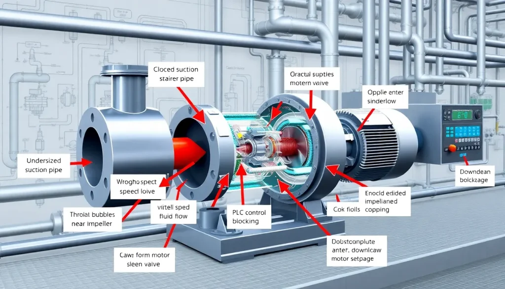
When diagnosing low flow or pressure, follow a systematic checklist. The most common twelve causes are:
- Clogged suction strainer or filter. Particulate buildup restricts inlet area, raising suction loss.
- Undersized suction pipe or excessive length. Increases friction loss and can cause suction lift beyond NPSH available.
- Air entrainment. Leaks in the suction line draw air, lowering density and effective head.
- Incorrect impeller diameter. A smaller impeller reduces both flow and head per the affinity laws.
- Improper pump speed. Motor slip, VFD mis‑programming, or worn bearings can reduce rpm.
- System valve throttling. Partially closed control valves shift the system curve leftward.
- Cavitation. Insufficient NPSH causes vapor bubbles that collapse, eroding the impeller and dropping head.
- High fluid viscosity. Viscous liquids increase internal friction, lowering Q for a given H.
- Wear or damage to impeller vanes. Erosion or corrosion changes the hydraulic geometry.
- Incorrect motor‑pump alignment. Mis‑alignment adds mechanical losses, reducing effective speed.
- Partial blockage downstream. Pipe scale, foreign objects, or improperly sized discharge piping can create back‑pressure.
- Control system set‑point errors. PLC or analog loops may be commanding a lower flow set point than required.
After identifying the likely cause, verify with measurements: check suction pressure, inspect strainer condition, run a pump curve test, and confirm motor speed with a tachometer. Corrective actions often involve cleaning, re‑sizing, adjusting VFD parameters, or replacing worn components.
Common Mistakes, Limits & Safety Notes
- Mixing US and SI units in the same calculation – always convert before applying formulas.
- Assuming linear Q–H relationship – the true curve follows a square‑root shape.
- Neglecting NPSH requirements – operating too close to vapor pressure leads to cavitation.
- Over‑relying on manufacturer curves without accounting for temperature‑viscosity corrections.
- Changing pump speed without re‑checking shaft seals – high speed can cause seal leakage.
- Ignoring motor overload protection – low flow can cause overheating.
- Installing a pump too far above the fluid source – excessive suction lift reduces NPSH available.
- Failing to account for pipe‑to‑pipe fittings – elbows and valves add significant head loss.
- Using a damaged impeller as a “quick fix” – efficiency loss may be > 30 %.
- Bypassing safety interlocks when troubleshooting – always isolate power and lock‑out/tag‑out.
FAQ
Why does my pump feel hot when the flow is low?
Low flow reduces the cooling water passing through the pump casing, causing the motor and bearings to run hotter. It can also indicate a blockage that forces the pump to work against higher head, increasing internal losses and temperature.
Can a partially closed valve cause both low flow and low pressure?
Yes. A throttling valve shifts the system curve left, limiting flow. Because the pump cannot develop its rated head at the reduced flow, the discharge pressure also drops, giving the appearance of low pressure.
How much suction pipe diameter can I reduce before affecting performance?
A rule of thumb is to keep the suction pipe diameter at least 1.5 times the impeller eye diameter. Reducing below this increases velocity head losses and can cut flow by 10‑15 %.
What is the minimum NPSH available for a water‑based pump?
For most water‑based centrifugal pumps, NPSH_available should be at least 1.5 m (5 ft) greater than NPSH_required to provide a safety margin against cavitation.
Why does my pump lose pressure after a few hours of operation?
Thermal expansion of the fluid can increase viscosity, and fouling of the suction screen can develop over time. Both raise internal resistance, lowering the pressure generated at a given speed.
Can a VFD cause low flow if programmed incorrectly?
Absolutely. If the VFD limits the maximum frequency below the pump’s design speed, the resulting lower rpm reduces flow according to the affinity law, often unnoticed until performance drops.
Is it safe to run a pump at a lower speed to fix low pressure?
Running slower reduces head, which may alleviate cavitation but also lowers flow. Verify that the new operating point still meets process requirements before making the change permanent.
How do I check for air entrainment in the suction line?
Measure suction pressure with a calibrated gauge; a reading above atmospheric but below expected static head indicates air. Additionally, listen for gurgling sounds and inspect for visible bubbles in the suction pipe.
Leave a Reply