
Short Answer
Key Formula / Key Facts Box
| Symbol | Meaning | US Unit | SI Unit | Plain‑English Restatement |
|---|---|---|---|---|
| ΔT | Temperature rise of the pump housing | °F | K | How much hotter the pump gets during operation. |
| P_in | Electrical input power to the motor | hp | kW | Power supplied to the motor. |
| P_out | Hydraulic power delivered to the fluid | hp | kW | Useful power that moves the liquid. |
| η_m | Combined motor‑pump efficiency | % | % | Fraction of input power that becomes fluid power. |
| ṁ | Mass flow rate of the fluid | lb/h | kg/s | How much fluid mass passes per unit time. |
| C_p | Specific heat capacity of the fluid | BTU/(lb·°F) | kJ/(kg·K) | Heat required to raise the fluid by one degree. |
Governing heat‑balance equation:
ΔT = frac{P_{in} – P_{out}}{dot m ; C_p}
In words: the temperature rise equals the net heat retained in the pump divided by the fluid’s ability to carry that heat away.
Overview — What It Is and Why It Matters
When a pump operates, electrical energy is transformed into mechanical rotation and then into hydraulic work. Inefficiencies—such as bearing friction, magnetic core losses, slip in induction motors, and hydraulic losses in the impeller—appear as heat. If the generated heat is not removed quickly enough, the pump casing, bearings, seals, and motor windings can exceed their design temperature limits. Over‑temperature degrades lubricants, causes seal extrusion, promotes cavitation, and can lead to sudden catastrophic failure. In process plants, an overheated pump often triggers interlocks, forces an unscheduled shutdown, and incurs costly downtime.
The Method — Derivation and Variants
Starting from the steady‑state first‑law energy balance for a pump:
(P_{in}=P_{out}+Q_{loss})
where (Q_{loss}) is the heat that must be rejected to the surroundings. Assuming the dominant removal path is convection to the pumped fluid, the heat flux can be expressed as:
(Q_{loss}=dot m C_p Delta T)
Re‑arranging yields the governing equation shown above. Two practical versions are used in the field:
- US‑customary: (Delta T[°F]=dfrac{(P_{in}[hp]-P_{out}[hp])times2545}{dot m[lb/h];C_p[BTU/(lb·°F)]})
- SI: (Delta T[K]=dfrac{(P_{in}[kW]-P_{out}[kW])}{dot m[kg/s];C_p[kJ/(kg·K)]})
The constant 2545 converts horsepower to BTU /h (1 hp = 2545 BTU /h). The equation assumes steady flow, constant fluid properties, and that external cooling (fans, jackets) is either absent or accounted for by subtracting a cooling term (Q_{cool}) from (Q_{loss}).
Worked Example
Example 1 – US Units
A 30 hp centrifugal pump moves water at 10 000 lb/h. The combined motor‑pump efficiency is 70 % and water’s specific heat is 1 BTU/(lb·°F). Determine the expected temperature rise of the pump housing.
- Hydraulic power: (P_{out}=η_m P_{in}=0.70times30;hp=21;hp).
- Net heat to be rejected: (P_{in}-P_{out}=30-21=9;hp).
- Convert to BTU/h: (9;hptimes2545=22,905;BTU/h).
- Apply the formula: (Delta T=dfrac{22,905}{10,000times1}=2.29;°F).
Result: The pump casing will be roughly 2.3 °F hotter than the inlet water.
Example 2 – SI Units
A 22 kW axial‑flow pump delivers 0.15 kg/s of a glycol‑water mixture ((C_p=3.8;kJ/(kg·K))) at an overall efficiency of 80 %.
- Hydraulic power: (P_{out}=0.80times22=17.6;kW).
- Heat retained: (P_{in}-P_{out}=22-17.6=4.4;kW).
- Temperature rise: (Delta T=dfrac{4.4}{0.15times3.8}=7.7;K).
Result: The pump and fluid temperature increase by about 8 K (≈14 °F).
Calculator
For rapid online computation, use the dedicated heat‑balance tool: Pump Temperature Rise Calculator.
Reference Values & Typical Ranges
- Combined motor‑pump efficiency: 60 %–85 % for most centrifugal designs (ISO 9906).
- Acceptable ΔT for metallic casings without auxiliary cooling: ≤30 °F (≈17 K).
- Typical water mass‑flow rates in plant service: 5 000–50 000 lb/h (0.6–6 m³/h).
- Internal convection heat‑transfer coefficient for water: 500–2 000 W/(m²·K) (ASME PTC‑19.1).
- Maximum bearing temperature per most bearing manufacturers: 250 °F (≈121 °C).
Application Guidance
When selecting a pump, compute the predicted ΔT and compare it with the manufacturer’s maximum case temperature. If the calculated rise approaches the limit, consider one or more of the following actions:
- Increase the mass‑flow rate (higher (dot m) carries more heat away).
- Choose a motor with higher efficiency or integrate a VFD to reduce part‑load losses.
- Install external cooling: fan‑forced air, water‑jacket, or heat‑sink plates.
- Select a pump with a larger hydraulic diameter or a more efficient impeller geometry to lower internal friction.
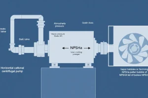
- Verify that the NPSH margin is sufficient; cavitation adds localized heating.
During commissioning, instrument bearing and housing temperatures with thermocouples or infrared probes and set alarms at 80 % of the design limit.
Common Mistakes, Limits & Safety Notes
- Ignoring motor losses. Only hydraulic power is sometimes considered; motor losses (15 %–30 % of input) can dominate the heat budget.
- Unit mismatches. Plugging US hp into an SI‑based formula (or vice‑versa) yields a temperature rise error of about a factor of 3.6.
- Assuming constant (C_p). Viscous fluids (glycol, oil) have temperature‑dependent specific heat; using a single value may underestimate ΔT at elevated temperatures.
- Neglecting auxiliary cooling. When a fan or jacket is present, the simple box equation over‑predicts temperature rise.
- Relying solely on pump curves. Manufacturer curves are usually measured with water at 68 °F; applying them to hotter or more viscous fluids without correction hides additional heat.
- Overlooking bearing cooling. Bearings are less effectively cooled than the housing; they can overheat even when the case temperature is within limits.
- Operating at low flow. Running below 30 % of design flow dramatically reduces convective heat removal, causing hot spots.
- Skipping regular cleaning. Scale or sludge on the impeller raises hydraulic losses and frictional heating.
FAQ
What are the most common signs that a pump is overheating?
Typical symptoms include rising bearing temperature alarms, increased motor current, reduced flow, audible whining, and discoloration of seals or oil.
Can increasing the pump flow rate reduce its temperature rise?
Yes. A higher mass flow carries more heat away, lowering ΔT, provided the system can handle the extra flow without excessive pressure or cavitation.
How does cavitation contribute to pump overheating?
Cavitation creates vapor bubbles that collapse violently, producing localized hot spots and additional friction, which adds to the overall heat load on the impeller and casing.
Is it safe to run a pump continuously at 90 % of its maximum temperature rating?
Operating that close to the limit leaves little margin for transient spikes; best practice is to keep steady‑state temperature below 80 % of the design maximum.
Do variable‑frequency drives affect pump heat generation?
VFDs improve motor efficiency at part‑load, reducing electrical losses and heat, but they also introduce switching losses that must be considered in the overall heat balance.
What maintenance actions help prevent thermal damage?
Regular impeller cleaning, bearing lubrication checks, fan operation verification, seal inspection, and calibration of temperature sensors are key preventive measures.
Why does a pump run hotter when the fluid viscosity increases?
Higher viscosity raises hydraulic losses (friction and turbulent dissipation), which converts more input power into heat, increasing the pump’s temperature rise.
Leave a Reply