
Short Answer
Key Formula / Key Facts Box
Euler’s Pump Equation (SI)
[ H = frac{U_2 V_{theta 2} – U_1 V_{theta 1}}{g} + frac{V_2^2 – V_1^2}{2g} ]
where (H) is the total head (m), (U) is the peripheral speed (m/s), (V_{theta}) is the tangential component of absolute velocity (m/s), (V) is the absolute velocity magnitude (m/s), and (g) is 9.80665 m/s².
Euler’s Pump Equation (US)
[ H_{ft} = frac{U_2 V_{theta 2} – U_1 V_{theta 1}}{g_c} + frac{V_2^2 – V_1^2}{2g_c} ]
with (g_c = 32.174,ft·lb_f/(lb_m·s^2)).
| Symbol | Meaning | US Unit | SI Unit | Plain‑English Restatement |
|---|---|---|---|---|
| H | Total head | ft | m | Energy per unit weight added to the fluid. |
| U | Impeller peripheral speed | ft/s | m/s | Speed of a point on the impeller rim. |
| Vθ | Tangential component of absolute velocity | ft/s | m/s | Swirl imparted to the fluid. |
| V | Absolute velocity magnitude | ft/s | m/s | Total speed of fluid particles. |
| g (or g_c) | Gravitational constant (or conversion factor) | ft/s² | m/s² | Standard acceleration due to gravity. |
Overview — What It Is and Why It Matters
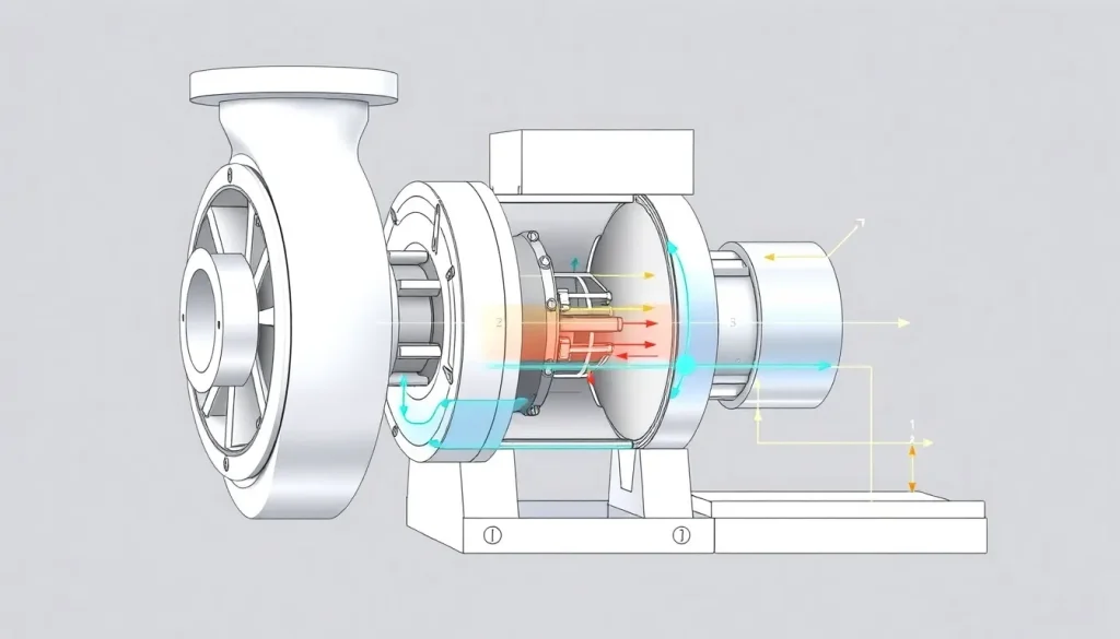
A centrifugal pump is a rotating‑machine that imparts kinetic energy to a liquid via a series of curved blades (the impeller). The kinetic energy is subsequently converted to pressure energy as the fluid decelerates in the volute or diffuser. Because the relationship between shaft power, flow rate, and head is predictable, centrifugal pumps dominate the bulk‑fluid handling market in water supply, HVAC, chemical processing, and many other industries.
From a design standpoint, the operating principle governs three critical decisions: selection of impeller diameter and speed, determination of required motor horsepower, and evaluation of system‑level constraints such as Net Positive Suction Head (NPSH). Errors in interpreting the head‑flow relationship can cause cavitation, premature wear, or catastrophic failure, leading to costly downtime.
The Method — Derivation and Variants
The derivation begins with the conservation of angular momentum for a control volume surrounding a single impeller blade. By applying the Euler turbomachinery equation, the change in the fluid’s tangential momentum equals the torque supplied by the shaft. The simplified form for a radial‑flow centrifugal pump (where inlet radius ≈ 0) reduces to:
SI: ( H = frac{U_2 V_{theta 2}}{g}) because (U_1) and (V_{theta 1}) are essentially zero at the eye of the impeller. The kinetic‑energy correction term ((V_2^2 – V_1^2)/2g) accounts for non‑ideal velocity profiles and is often expressed as a “velocity coefficient” in empirical pump curves.
In the United States, the same relationship is expressed using the gravitational conversion factor (g_c) to keep units consistent when horsepower is calculated:
US: ( H_{ft} = frac{U_2 V_{theta 2}}{g_c}).
When the pump operates at off‑design points, the slip factor (σ) and the discharge coefficient (C_d) modify the ideal velocity terms, giving rise to several variants of the basic equation used in CFD‑based design versus catalog‑based selection.
Worked Example
Example 1 – SI System
A chemical plant requires 0.12 m³/s of water at a total head of 45 m. The selected pump has a 0.35 m impeller radius rotating at 1800 rpm. Compute the theoretical head using Euler’s equation and compare with the required head.
- Convert rpm to rad/s: (N = 1800,rpm = 1800timesfrac{2pi}{60}=188.5,rad/s).
- Peripheral speed: (U_2 = r_2,N = 0.35times188.5 = 65.98,m/s).
- Assume a tangential velocity coefficient (K_t = 0.9). Then (V_{theta 2}=K_t,U_2 = 0.9times65.98 = 59.38,m/s).
- Neglect inlet swirl ((U_1 V_{theta 1}=0)) and kinetic‑energy correction (≈0.5 m). Apply Euler:
[ H = frac{U_2 V_{theta 2}}{g}=frac{65.98times59.38}{9.80665}=399,m]. - The theoretical head far exceeds the system requirement, indicating that the pump will operate at a point far left of the curve where efficiency is high. Selecting a smaller impeller or reducing speed will bring the operating point closer to 45 m.
Example 2 – US Customary System
A municipal water system needs 250 gpm at 120 ft of head. The candidate pump has a 10‑in impeller (radius 0.417 ft) rotating at 1750 rpm. Determine the shaft horsepower required, assuming 75 % overall efficiency.
- Convert rpm to rad/s: (N = 1750timesfrac{2pi}{60}=183.3,rad/s).
- Peripheral speed (ft/s): (U_2 = r_2 N = 0.417times183.3 = 76.4,ft/s).
- Assume (K_t = 0.85); (V_{theta 2}=0.85times76.4=64.9,ft/s).
- Theoretical head (ft): ( H = frac{U_2 V_{theta 2}}{g_c}=frac{76.4times64.9}{32.174}=154,ft).
- Actual head needed is 120 ft, so the pump will operate at about 78 % of its ideal head.
- Hydraulic power: (P_h = rho g H Q = 62.4,lb/ft^3 times 120,ft times 250,gpmtimesfrac{1,ft^3}{7.48,gal}timesfrac{1}{550}approx 3.9,hp).
- Accounting for 75 % efficiency: (P_{shaft}=frac{P_h}{0.75}approx5.2,hp).
Calculator
For quick verification, use an online total dynamic head calculator: http://pumpcalcs.com/calculators/total-dynamic-head/
Reference Values & Typical Ranges
- Impeller diameters: 2 in – 48 in (0.05 m – 1.2 m) for most industrial centrifugal pumps.
- Rotational speeds: 350 rpm – 3600 rpm (standard motor speeds 1800 rpm & 3600 rpm).
- Specific speed (N_s) ranges:
N_s (US) Typical Impeller Type Application 500‑1500 Radial‑flow High head, low flow (e.g., boiler feed) 1500‑3000 Mixed‑flow Medium head/flow (e.g., water‑treatment) 3000‑8000 Axial‑flow Low head, high flow (e.g., cooling‑tower circulation) - Overall efficiency: 60 % – 85 % for standard oils; up to 90 % for high‑performance designs.
- Net Positive Suction Head Required (NPSHr): typically 0.5 – 2 m (1.5 – 6 ft) depending on impeller speed.
Application Guidance
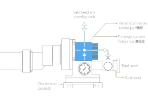
When integrating a centrifugal pump into a process loop, start with the system curve (head versus flow) derived from pipe friction, fittings, and elevation changes. The intersection of the system curve with the pump’s characteristic curve defines the operating point. Adjust impeller diameter (trim) or motor speed (VFD) to shift the pump curve horizontally or vertically, respectively, to achieve the desired NPSH margin and efficiency.
Field‑judgment adjustments include accounting for temperature‑induced viscosity changes, which affect NPSHr, and recognizing that slurry or abrasive fluids may necessitate a larger clearance or a special‑material impeller. For critical applications, a performance test (e.g., ISO 9906) validates the manufacturer’s curve under actual suction conditions.
Common Mistakes, Limits & Safety Notes
- Unit mix‑up: Using SI values in an equation that requires (g_c) leads to a 3.28× error in head.
- Neglecting slip: Assuming (V_{theta 2}=U_2) overestimates head, especially at high speeds.
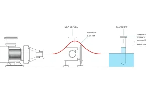
- Undersizing NPSH: Selecting a pump with NPSHr close to available NPSHa invites cavitation and impeller damage.
- Operating far off the Best Efficiency Point (BEP): Causes excessive vibration, seal wear, and reduced lifespan.
- Ignoring temperature effects: Fluid density and viscosity change the hydraulic power calculation.
- Improper shaft alignment: Misalignment adds radial loads, leading to bearing failure.
- Exceeding the rated speed: Surpassing the maximum (U) can cause blade fatigue and catastrophic rupture.
- Safety clearance: Never work on a pump that is still connected to its drive; lock‑out/tag‑out per OSHA 1910.147 is mandatory.
FAQ
Why does a centrifugal pump develop pressure instead of just increasing fluid velocity?
The impeller adds kinetic energy to the fluid; as the fluid passes through the diffuser or volute, this kinetic energy is converted to static pressure according to Bernoulli’s principle, resulting in a rise in total head.
Can a centrifugal pump handle viscous liquids like oil?
Yes, but viscosity raises the required NPSH and reduces efficiency. Manufacturers provide corrected performance curves for fluids up to about 10 cSt; beyond that, a positive‑displacement pump is often more economical.
What is the Best Efficiency Point (BEP) and why is it important?
BEP is the flow rate at which the pump operates at its highest hydraulic efficiency. Designing the system to run near BEP minimizes wear, vibration, and energy consumption.
How does impeller trimming affect pump performance?
Trimming reduces the impeller diameter, which shifts the pump curve downward and to the left, decreasing head and flow proportionally. It is a common method to fine‑tune a pump to a specific system requirement.
Is it safe to operate a centrifugal pump above its rated speed?
Exceeding the rated speed increases peripheral velocity, raising the risk of blade fatigue, excessive vibration, and cavitation. Most standards prohibit operation beyond the maximum permissible speed without re‑certification.
What role does a Variable Frequency Drive (VFD) play with centrifugal pumps?
A VFD varies motor speed, allowing the pump to follow changing system demands while maintaining high efficiency. It also reduces mechanical stress during start‑up and provides soft‑starting capability.
How do you calculate the hydraulic power needed for a centrifugal pump?
Hydraulic power (kW) = ρ · g · H · Q, where ρ is fluid density, g is gravitational acceleration, H is total head, and Q is flow rate. Multiply by 1/efficiency to obtain shaft power.
What is cavitation and how can it be prevented in centrifugal pumps?
Cavitation occurs when local pressure falls below the fluid’s vapor pressure, forming vapor bubbles that collapse and damage the impeller. Prevent it by ensuring sufficient NPSHa, reducing suction velocity, and avoiding excessive impeller speeds.
Leave a Reply