
Short Answer
Key Formula / Key Facts Box
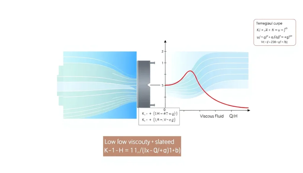
Viscosity correction factor (Kμ) – scales the water‑based performance data to a higher‑viscosity fluid:
K_{mu}=frac{1}{1+aleft(frac{mu}{mu_{ref}}right)^{b}}
| Symbol | Meaning | US unit | SI unit | Plain‑English |
|---|---|---|---|---|
| K_{mu} | Viscosity correction factor | – | – | Multiplier that reduces rated flow, head, or efficiency for a given viscosity. |
| mu | Fluid dynamic viscosity | cP (centipoise) | mPa·s | Measure of fluid’s resistance to shear. |
| mu_{ref} | Reference viscosity (water at 68 °F / 20 °C) | 1 cP | 1 mPa·s | Baseline viscosity used by pump manufacturers. |
| a,b | Empirical constants (ISO 5199: a≈0.02, b≈0.6 for efficiency; a≈0.10, b≈0.5 for flow) | – | – | Shape the correction curve; values differ for Q, H, and η. |
In plain English: as the fluid becomes thicker, the factor Kμ drops below 1, so the actual flow, head, and efficiency are the rated values multiplied by Kμ.
Overview — What It Is and Why It Matters
Centrifugal pumps are calibrated with water because its viscosity (≈1 cP at 20 °C) yields the highest hydraulic efficiency. When the pumped liquid is more viscous—oil, syrup, or slurry—the internal friction raises the hydraulic losses in the impeller passages and volute. The practical consequences are:
- Reduced flow rate (Q) at a given speed.
- Lower developed head (H) for the same rotational speed.
- Decline in overall efficiency (η), which raises motor power demand and operating temperature.
- Increased Net Positive Suction Head required (NPSH_R), raising cavitation risk.
Ignoring viscosity can lead to undersized motors, premature bearing wear, or even catastrophic pump failure. Engineers therefore apply a derating factor—derived from the formula above or from manufacturer‑provided curves—to guarantee that the pump will meet system requirements under the actual fluid conditions.
The Method — Derivation and Variants
The starting point is the affinity laws for an ideal, incompressible, low‑viscosity fluid:
[ Q propto N D^{3},quad H propto N^{2} D^{2},quad P propto N^{3} D^{5} ]
where N is speed and D impeller diameter. These relations assume that the Reynolds number is high enough that viscous forces are negligible.
When viscosity rises, the Reynolds number drops:
[ Re = frac{rho N D^{2}}{mu} ]
Below a critical Reynolds number (≈10⁴ for most impellers), the flow becomes laminar‑dominated and the above proportionalities no longer hold. Empirical studies (ISO 5199, API 610) showed that the deviation can be captured by a multiplicative factor Kμ applied to each performance parameter.
Derivation (simplified):
- Start with the water‑based head curve: H₀(Q₀).
- Introduce a viscous loss term proportional to μ^{b} (b≈0.5‑0.6) based on dimensional analysis.
- Combine with the water curve to obtain H = Kμ·H₀, and similarly for Q and η.
Two common variants appear in practice:
- Flow‑only correction (used when the system is flow‑controlled):
K_Q = 1 / (1 + a_Q (μ/μ_ref)^{b_Q}) with a_Q≈0.10, b_Q≈0.5.
- Efficiency correction (used for motor sizing):
K_η = 1 / (1 + a_η (μ/μ_ref)^{b_η}) with a_η≈0.02, b_η≈0.6.
Both are dimensionless and reduce to 1 when μ=μ_ref (water). The constants differ among manufacturers, so the safest approach is to consult the pump’s viscosity‑correction chart and, if unavailable, use the ISO‑based approximations above.
Worked Example
Example 1 – US customary units
A 2‑stage centrifugal pump is rated at 100 GPM delivering 150 ft of head at 1750 rpm with 70 % efficiency when pumping water (μ_ref=1 cP). The system will handle a light oil of μ=10 cP at the same temperature. Determine the derated flow, head, and motor power.
- Compute the viscosity ratio: μ/μ_ref = 10/1 = 10.
- Apply the flow correction factor (a_Q=0.10, b_Q=0.5):
K_Q = 1 / (1 + 0.10·10^{0.5}) = 1 / (1 + 0.10·3.162) = 1 / (1 + 0.316) = 0.760.
- Derated flow: Q_actual = K_Q·Q_rated = 0.760·100 GPM = 76 GPM.
- Apply the head correction factor (same a_H≈0.10, b_H≈0.5): K_H = 0.760 (for many pumps head follows flow).
- Derated head: H_actual = 0.760·150 ft = 114 ft.
- Efficiency correction (a_η=0.02, b_η=0.6):
K_η = 1 / (1 + 0.02·10^{0.6}) = 1 / (1 + 0.02·3.981) = 1 / (1 + 0.0796) = 0.927.
- Actual efficiency: η_actual = K_η·η_rated = 0.927·0.70 = 0.649 (≈65 %).
- Hydraulic power: P_h = ρ·g·Q·H / (3960·η). Using ρ≈58.5 lb/ft³ for oil,
P_h = (58.5·32.2·76·114) / (3960·0.649) ≈ 1,560 hp.
- Motor rating should be rounded up, e.g., 1,800 hp motor.
Example 2 – SI units
A 30 kW, single‑stage pump delivers 0.05 m³/s at 30 m head with water (μ_ref=1 mPa·s). The fluid is a glycerin‑water blend of μ=5 mPa·s. Find the derated head.
- Viscosity ratio = 5.
- Use flow correction (a_Q=0.10, b_Q=0.5): K_Q = 1/(1+0.10·5^{0.5}) = 1/(1+0.10·2.236) = 0.819.
- Derated flow: Q_actual = 0.819·0.05 = 0.0409 m³/s.
- Head correction (same factor): H_actual = 0.819·30 = 24.6 m.
- Efficiency correction (a_η=0.02, b_η=0.6): K_η = 1/(1+0.02·5^{0.6}) = 1/(1+0.02·3.162) = 0.938.
- Actual efficiency: η_actual = 0.938·0.80 = 0.75 (75 %).
- Hydraulic power: P_h = ρ·g·Q·H / η (ρ≈1050 kg/m³ for the blend)
P_h = (1050·9.81·0.0409·24.6)/0.75 ≈ 1,380 W ≈ 1.38 kW.
- Motor selection: a 2 kW motor provides adequate margin.
Calculator
For quick on‑line calculations, see Pump Performance Calculator. It includes a built‑in viscosity correction module.
Reference Values & Typical Ranges
- Water at 20 °C: μ = 1 mPa·s (1 cP) – baseline.
- Light mineral oil (25 °C): μ ≈ 15–30 cP.
- Heavy gear oil (40 °C): μ ≈ 150–300 cP.
- Viscosity correction factor Kμ is usually >0.9 for μ<5 cP, 0.7–0.9 for 5–50 cP, and 50 cP.
- Typical derating rule of thumb (ISO 5199): Reduce flow by 2 % for each 1 cP increase above 1 cP up to 10 cP; beyond that, use the empirical formula above.
Application Guidance
When specifying a centrifugal pump for a viscous fluid, follow these steps:
- Identify the fluid’s dynamic viscosity at operating temperature.
- Obtain the pump’s water‑based performance curve from the manufacturer.
- Apply K_Q, K_H, and K_η to the rated values.
- Check the resulting NPSH_R against the system’s NPSH_A; increase suction head or lower speed if necessary.
- Re‑size the motor using the derated hydraulic power and add a 10‑15 % safety margin.
- If the corrected flow falls below the system’s minimum, select a larger impeller or a pump designed for higher viscosity (e.g., “high‑viscosity” series).
Field‑adjustments: In practice, temperature changes alter μ dramatically. Install temperature‑compensated viscosity sensors and use a programmable PLC to adjust pump speed (VFD) in real time, keeping Kμ within the designed envelope.
Common Mistakes, Limits & Safety Notes
- Mixing units – inserting cP into a formula calibrated for mPa·s yields a factor ten too low.
- Using water curves without correction – leads to under‑powered motors and premature cavitation.
- Assuming constant Kμ across the entire curve – Kμ actually varies with flow; manufacturers provide separate curves for Q, H, and η.
- Neglecting temperature dependence – viscosity can change 30 % per 10 °C; always reference the fluid’s temperature‑viscosity chart.
- Applying the formula beyond its validity – ISO 5199 is calibrated for 1 cP ≤ μ ≤ 200 cP; for thicker fluids (e.g., tar), use positive‑displacement pumps.
- Over‑derating the motor – excessive safety margin can cause over‑heating and unnecessary energy cost.
- Ignoring NPSH_R increase – higher viscosity raises required suction head; failure may cause cavitation damage.
- Forgetting to re‑check seals and bearings – higher torque from viscous loads accelerates wear.
FAQ
Why does a higher viscosity reduce the flow rate of a centrifugal pump?
Viscosity increases internal friction in the impeller passages, converting more mechanical energy into heat rather than kinetic energy. This reduces the net kinetic energy imparted to the fluid, so for the same rotational speed the volumetric flow drops.
Can I use the pump’s water curve without any correction for light oil (≈5 cP)?
For fluids with μ up to about 5 cP the correction factor Kμ is typically >0.95, so the error is often within acceptable engineering tolerance. However, for precise motor sizing or cavitation‑critical applications, applying the small correction is recommended.
How do I determine the empirical constants a and b for my pump?
Most manufacturers publish viscosity‑correction charts that embed a and b. If unavailable, the ISO 5199 default values (a≈0.02, b≈0.6 for efficiency; a≈0.10, b≈0.5 for flow) provide a reasonable estimate.
Does increasing pump speed compensate for viscosity losses?
Increasing speed raises flow and head according to the affinity laws, but it also raises NPSH_R and motor power dramatically. A modest speed increase may recover some capacity, but it often leads to higher wear and may still not meet efficiency targets.
When should I switch from a centrifugal pump to a positive‑displacement pump?
If the fluid viscosity exceeds the practical limit of centrifugal pumps (≈200 cP) or the required flow is very low with high pressure, a positive‑displacement pump offers constant flow independent of viscosity and is usually the safer choice.
How does temperature affect viscosity correction?
Viscosity typically drops about 2‑3 % per 10 °C rise for liquids. Because Kμ depends on the viscosity ratio, a temperature change can shift Kμ by several percent. Always reference the fluid’s temperature‑viscosity curve and adjust the correction accordingly.
Is the viscosity correction factor the same for head and efficiency?
No. Head, flow, and efficiency each have their own empirical constants because viscous losses affect them differently. Manufacturers often provide separate K_Q, K_H, and K_η curves.
What safety issues arise if I ignore viscosity when selecting a pump?
Ignoring viscosity can cause undersized motors, excessive heating, cavitation, and premature seal or bearing failure. In extreme cases, the pump may seize or suffer catastrophic impeller damage.
Leave a Reply