
Short Answer
Key Formula / Key Facts Box
Governing relation for a closed hydronic loop:
Hpump = Σhf + Σhfit + Σhvalve + Σhequip + Σhcontrol
Equivalently, Hpump = ΔPdynamic / (ρg). For a complete closed circuit, the net static-elevation term is zero because the loop returns to the same elevation.
| Symbol | Meaning | US unit | SI unit |
|---|---|---|---|
| Hpump | Required pump differential head | ft w.g. | m w.g. |
| hf | Pipe friction loss | ft w.g. | m w.g. |
| hfit | Fittings and minor losses | ft w.g. | m w.g. |
| hvalve | Valves, strainers, and balancing loss | ft w.g. | m w.g. |
| hequip | Coils, boilers, chillers, and heat exchangers | ft w.g. | m w.g. |
| hcontrol | Control-valve loss at design flow | ft w.g. | m w.g. |
| ΔPdynamic | Total dynamic pressure loss | psi | kPa |
| ρ | Fluid density | lb/ft³ | kg/m³ |
| g | Gravitational acceleration | ft/s² | m/s² |
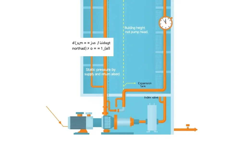
Plain-English restatement: The pump supplies only the pressure needed to overcome flow resistance around the loop. The building height is handled by fill pressurization, expansion control, and equipment pressure ratings, not by adding the building height to the pump head.

Overview — What It Is and Why It Matters
This article uses the common encyclopedic meaning of a closed hydronic loop: a sealed heating or chilled-water piping circuit in which the same water or glycol solution is continuously recirculated, with no free water surface open to atmosphere. It does not apply directly to open-loop cooling-tower spray systems, open tanks, or domestic-water boosters, where static lift can be a real pump-head component.
In a closed hydronic loop, the circulator is not a lift pump. It does not lift a new batch of water from the basement to the roof on every pass. The loop is filled and pressurized, and the same fluid travels up the supply riser and back down the return riser. The static pressure at the pump suction includes the weight of the water column above it, but the return column pushes back with nearly the same static pressure. Around a complete circuit, the net elevation change is zero, so the pump differential head is governed by dynamic losses: pipe friction, fittings, valves, coils, chillers, boilers, strainers, and control valves.
Confusing building height with pump head is one of the most common hydronic design errors. If a designer selects a pump for 300 ft of head because the building is 300 ft tall, while the actual index circuit requires 80 ft, the pump will run far from its best efficiency point. The result can be excessive pressure, valve noise, erosion, poor control, low delta-T, and wasted energy. Building height still matters, but it belongs in a different calculation: fill pressure, expansion-tank sizing, pressure-reducing valve zoning, component pressure ratings, relief-valve settings, and net positive suction head. The key is to separate static pressure from pump differential pressure.
The Method — Derivation and Variants
Begin with the steady-flow energy equation for incompressible flow. For a pump in a piping circuit, the head added by the pump equals the sum of head losses plus any change in elevation, pressure, and velocity between the chosen points. When the control volume starts at a point in the loop and returns to the same point, elevation, velocity, and static pressure changes around the complete circuit cancel. The practical result is Hpump = ΣhL, where ΣhL is the sum of dynamic head losses around the index circuit at design flow.
Each loss component can be expressed as a resistance: pipe friction hf = f(L/D)(v²/2g); fittings hfit = K(v²/2g); and equipment or valves h = ΔP/(ρg). The index circuit is the complete supply-and-return route with the greatest total pressure loss, not the sum of all parallel branches. In a closed loop, the static height from pump to highest point appears in gauge pressure and fill pressure, but it does not appear as a net term in the pump differential head.
| Form | Expression | Use |
|---|---|---|
| US customary | Hp (ft w.g.) = Σ losses (ft w.g.) = 2.31 × ΔPloss (psi) / SG | Water or glycol; SG = 1 for water |
| SI | Hp (m w.g.) = Σ losses (m w.g.) = ΔPloss (kPa) / (9.81 × SG) | Use density for exact glycol mixtures |
The constant 2.31 comes from the conversion between psi and feet of water for water at ordinary HVAC temperatures; 1 psi is approximately 2.31 ft w.g. The SI constant 9.81 comes from gravitational acceleration in m/s² when pressure is in kPa and density is in kg/m³. For glycol solutions, use specific gravity or density and check viscosity effects on friction. Variants include constant-flow and variable-flow closed loops, primary-secondary pumping, and distributed pumping. In all of these closed-loop variants, building height is not added to pump differential head. Open-loop variants are different: static lift to a free surface or discharge elevation must be included.
Worked Example
Example 1 — US customary. A 10-story building has a closed hot-water loop with about 100 ft between the pump and the highest coil. Design flow is 200 gpm. At design flow, calculated losses are: pipe 35 ft, fittings 8 ft, valves and balancing 12 ft, coils and AHU 15 ft, and control valve 25 ft. Total dynamic head = 35 + 8 + 12 + 15 + 25 = 95 ft w.g. Required pump differential head is 95 ft, not 100 ft and not 195 ft. Pump pressure differential = 95 / 2.31 = 41.1 psi. With 10 psig minimum at the top, static pressure at the base = 10 + 0.433 × 100 = 53.3 psig. Pump discharge gauge pressure is approximately 53.3 + 41.1 = 94.4 psig. The 100 ft height affects gauge readings and fill pressure, but not the 95 ft pump head.
Example 2 — SI. The same system has a height of 30.5 m. Design losses are: pipe 10.5 m, fittings 2.4 m, valves and balancing 3.6 m, equipment 4.5 m, and control valve 7.5 m. Total dynamic head = 10.5 + 2.4 + 3.6 + 4.5 + 7.5 = 28.5 m w.g. Pump differential pressure = ρgH = 1000 × 9.81 × 28.5 = 279,585 Pa ≈ 280 kPa, or 2.80 bar. With 70 kPa minimum at the top, static pressure at the base = 70 + 1000 × 9.81 × 30.5 / 1000 = 70 + 299 = 369 kPa. Pump discharge pressure is approximately 369 + 280 = 649 kPa. Again, building height sets static pressure and component ratings, while the pump differential is 28.5 m or 280 kPa.
Calculator
Use a total dynamic head calculator such as pumpcalcs.com Total Dynamic Head Calculator to sum friction, fittings, valves, equipment, and control-valve losses at design flow. Enter the closed-loop losses, not the building height. For glycol, adjust density and viscosity.
Reference Values & Typical Ranges
Use these values as sanity checks only; calculate project-specific values.
| Parameter | Typical value or rule | Notes |
|---|---|---|
| Static pressure gradient for water | About 0.433 psi/ft; 9.81 kPa/m | Sets gauge pressure, not closed-loop pump differential head |
| Minimum pressure at top of closed loop | Often 5–15 psig; 35–100 kPa | Many examples use 10 psig; verify air control and equipment needs |
| Common closed-loop pump differential | Roughly 10–100 ft w.g.; 30–300 kPa | Wide range; high-loss or large systems can exceed this |
| Control-valve loss at design | Several psi to tens of ft w.g. | Depends on valve authority and balancing approach |
| Pipe velocity | Often 2–8 ft/s; 0.6–2.4 m/s | Not universal; noise, erosion, and pressure loss constrain selection |
| Pump location | Often lowest floor near boilers or chillers | Improves NPSH margin but increases lower-floor static pressure |
Grundfos notes that heating systems are hydraulically closed and the building height need not be taken into account when designing the pump; pipework resistance and individual resistances are the critical factors. Powerhouse gives a 45 ft rise producing about 19.5 psig static at the base, while the pump head must cover loop pressure loss. ACHR News illustrates a 150 ft rise with about 10 psig at the top, fill pressure near 75 psig, and static head excluded from closed-loop pump-head calculations. H2X Engineering similarly identifies the index circuit as the greatest-loss route and notes that static building height is generally not added in a closed recirculation loop.
Application Guidance
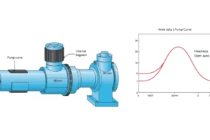
In real systems, pump differential head follows the system curve. At design flow, the pump must produce enough head to move water through the index circuit, including control valves at their design pressure drop. In variable-flow systems, as valves close, the pump head falls along the system curve; variable-speed control shifts the pump curve. Selection should compare the pump curve with the calculated system curve at design and part-load conditions, check efficiency and non-overloading power, verify NPSH margin, and confirm casing and component pressure ratings.
Building height changes the pressure environment. Lower floors in a tall building see higher static pressure than upper floors. The fill valve, expansion tank, pressure-reducing valves, relief valves, and pressure zoning must handle that static pressure. High-rise systems may use pressure zones, plate heat exchangers, break tanks, or distributed pumping, not because the pump must lift the water to the roof, but because static pressure and equipment ratings must be managed. Field judgment includes using the real index circuit, including dirty filters and strainers, checking glycol concentration, accounting for altitude and water temperature, and confirming that control valves can authority the flow without excessive noise. Do not add the losses of parallel branches together; use the worst complete route.
Common Mistakes, Limits & Safety Notes
- Adding building height directly to pump head in a closed hydronic loop. The net static elevation around the complete circuit is zero.
- Using pump discharge gauge pressure as pump head. The pump head is the differential pressure across the pump, not the absolute or gauge pressure at one flange.
- Applying the closed-loop rule to open systems. Cooling-tower spray loops, open tanks, and some boosters can require static lift.
- Summing losses from all parallel branches instead of identifying the index circuit with the greatest complete-route loss.
- Omitting control valves, balancing valves, strainers, check valves, coils, chillers, boilers, and heat exchangers from the dynamic-loss sum.
- Mixing units: psi versus ft w.g., kPa versus m w.g., 2.31 versus 0.433, and water-specific gravity versus glycol density.
- Ignoring static pressure effects on lower floors, expansion tanks, pressure-reducing valves, relief valves, and component maximum allowable working pressure.
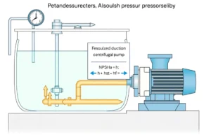
- Neglecting NPSH and pump location. A pump at the base may have good suction pressure, but high water temperature or poor piping can still cause cavitation.
- Oversizing the pump by using building height as head. This can cause valve noise, poor control, erosion, low delta-T, and wasted energy.
- Treating this article as a substitute for project engineering. Overpressure can damage equipment or create safety hazards; verify relief protection, pressure ratings, and applicable codes.
FAQ
Does pump head have to equal building height in a closed hydronic loop?
No. In a closed loop, the supply and return static columns balance, so the pump does not need to lift water to the roof. Pump head is based on dynamic losses around the index circuit. Building height affects fill pressure and component ratings, not the pump differential head. Oversizing to building height causes waste and poor control.
Why does building height not add to pump head?
Because the loop is full and returns to the same elevation. The pump circulates the same water rather than lifting a new batch each cycle. The lower static pressure is higher, but the return column pushes back. The net elevation change around the complete circuit is zero, leaving friction and component losses as pump head.
What is pump head based on in a closed-loop heating system?
It is the sum of pressure losses around the index circuit at design flow: pipe friction, fittings, valves, coils, boilers or chillers, strainers, and the control valve. Use the greatest-loss complete route, not the sum of parallel branches. Convert component pressure drops to head using fluid density.
Does building height matter at all for hydronic pumps?
Yes, but differently. Height sets static fill pressure, expansion-tank sizing, pressure ratings, relief settings, lower-floor pressures, and NPSH. High-rise systems may need pressure zones or pressure-reducing valves. It does not directly add to pump differential head in a closed loop.
How do I calculate pump head for a closed hydronic loop?
Identify the index circuit, calculate losses at design flow, and sum them in ft w.g. or m w.g. Convert pressure drops using H = ΔP/(ρg). Include the control valve at design pressure drop. Compare with the pump curve and check efficiency, NPSH, and pressure ratings. Do not add building height.
When is static lift added to pump head?
In open-loop systems where water is lifted to a free surface or discharged at a higher elevation, static lift must be added. Examples include cooling-tower spray loops, open tanks, and some domestic boosters. A sealed closed hydronic loop is different because the return static column balances the supply column.
Why are circulation pumps often located at the bottom of high-rise buildings?
Lower placement increases suction pressure, helping prevent cavitation and providing NPSH margin. It also keeps pumps near boilers and chillers. However, lower floors and equipment then see high static pressure, so pressure ratings, relief valves, and zoning must be checked. Pump head still depends on loop losses, not height.
Can I just select a pump for the building height as a rule of thumb?
No. That rule often produces severe oversizing in closed loops. A 300 ft building may need only 60–120 ft of pump head, depending on components and flow. Calculate index-circuit losses and check the pump curve. Oversizing can cause noise, valve erosion, poor control, and energy waste.

Leave a Reply