Short Answer
Key Formula / Key Facts Box
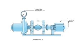
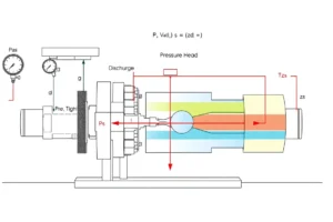
Governing field-test formula: TDH = (p_d − p_s)/γ + (v_d² − v_s²)/(2g) + (z_d − z_s), where γ = ρg = SG·ρ_w·g.
| Symbol | Meaning | US unit | SI unit |
|---|---|---|---|
| TDH | Total dynamic head developed by the pump | ft | m |
| p_d − p_s | Discharge minus suction gauge pressure | psi | kPa or Pa |
| γ | Specific weight of the pumped liquid | lb/ft³ | N/m³ |
| v_d, v_s | Mean velocity at discharge and suction measurement taps | ft/s | m/s |
| z_d, z_s | Tap elevation above the chosen datum | ft | m |
Simplified water form: TDH_ft ≈ 2.31 × (p_d − p_s)_psi / SG; TDH_m ≈ (p_d − p_s)_kPa / (9.81 × SG). Add velocity-head and elevation corrections when taps differ in size or height.
Plain-English restatement: The duty point is the measured flow paired with the total head the pump actually develops after pressure, velocity, elevation, and fluid-density corrections.
Overview — What It Is and Why It Matters
Chosen scope: This article uses the common encyclopedic meaning of pump duty point for a rotodynamic pump: the flow-head pair where the pump performance curve intersects the system resistance curve under actual field conditions. For positive-displacement pumps, flow is governed mainly by speed and slip, but the same measurement and correction discipline applies.

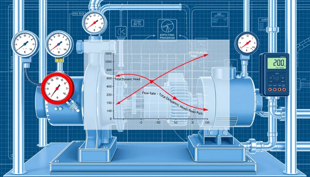
A duty point is not a single pressure or a single flow. It is a paired operating condition, usually stated as flow rate, total dynamic head, speed, efficiency, and power. The pump must operate on its published head-flow curve for the actual speed and impeller diameter; the system must operate on its resistance curve. The intersection is the duty point. Field test data let engineers check whether the real intersection matches the design point, or whether wear, speed error, fouling, valve position, air, or changed demand has moved it.
Why it matters: a pump far left of its best efficiency point can suffer recirculation, high radial thrust, overheating, and seal or bearing distress; a pump far right can cavitate, overload the motor, or run with low efficiency. Confirming the duty point first prevents replacing a healthy pump when the real fault is a closed valve, dirty strainer, entrained air, or wrong VFD setting. It also supports energy audits, acceptance tests, troubleshooting, and root-cause failure analysis.
The Method — Derivation and Variants
Start with the steady-flow energy equation between the suction and discharge measurement taps. Convert gauge pressures to pressure head, add velocity-head difference, and add elevation difference to the chosen datum, normally the pump centerline or discharge flange centerline. The result is total dynamic head. For a liquid of specific gravity SG, pressure head is Δp/γ, where γ = SG × ρ_w × g.
| Calculation step | US customary form | SI form |
|---|---|---|
| Pressure head | (p_d − p_s)_psi × 2.31 / SG | (p_d − p_s)_kPa / (9.81 × SG) |
| Velocity-head difference | (v_d² − v_s²) / (2 × 32.174) ft | (v_d² − v_s²) / (2 × 9.81) m |
| Elevation difference | z_d − z_s ft | z_d − z_s m |
| Flow from velocity | Q_gpm = V_ft/s × A_ft² × 448.831 | Q_m³/s = V_m/s × A_m² |
The constant 2.31 ft per psi is a convenient water conversion at ordinary temperatures; use 2.31/SG for liquids other than water. The SI constant 9.81 is gravitational acceleration, and the kPa form already includes the 1000 factor for kilopascals. If pressures are in Pa, use Δp_Pa/(9810 × SG). If flow is measured directly, skip the velocity-to-flow step but still include velocity head when suction and discharge pipe sizes differ.
Hydraulic power and efficiency are useful cross-checks: P_hyd_hp = Q_gpm × TDH_ft × SG / 3960; P_hyd_kW = Q_m³/s × TDH_m × SG × 9.81; pump efficiency = P_hyd / P_shaft. Use shaft power, not electrical input, unless motor efficiency is known. For a VFD or changed motor speed, correct the measured point to the curve speed with the affinity laws: Q₂ = Q₁ × (N₂/N₁) and H₂ = H₁ × (N₂/N₁)². For positive-displacement pumps, use Q ≈ displacement × speed × volumetric efficiency and take head from the system pressure requirement.
Worked Example
US customary example. A clean-water pump is rated 250 gpm at 85 ft and 1750 rpm. Field readings at stable operation: suction 3 psig, discharge 40 psig, flow 250 gpm, speed 1750 rpm, electrical input 7.1 kW, motor efficiency 0.90, SG 1.0. Assume the gauge taps are at the same elevation and the same pipe size, so velocity-head and elevation corrections are negligible.
- Pressure difference: 40 − 3 = 37 psi.
- Pressure head: 37 × 2.31 / 1.0 = 85.5 ft.
- TDH: 85.5 ft after negligible corrections.
- Hydraulic power: 250 × 85.5 × 1.0 / 3960 = 5.40 hp.
- Shaft power: 7.1 kW × 1.341 × 0.90 = 8.57 hp.
- Pump efficiency: 5.40 / 8.57 = 0.63, or 63%.
The measured point is approximately 250 gpm at 85.5 ft. Compare it with the manufacturer curve at 1750 rpm. If the curve gives about 85 ft at 250 gpm, the duty point is confirmed within field uncertainty; if not, check gauge calibration, tap location, actual speed, impeller condition, air entrainment, and valve position before condemning the pump.
SI example. A pump is rated 15 L/s at 25 m and 1450 rpm. Field data: suction 30 kPa, discharge 280 kPa, flow 14.2 L/s, speed 1450 rpm, electrical input 5.4 kW, motor efficiency 0.90, SG 1.0. Taps are at equal elevation and equal diameter.
- Pressure difference: 280 − 30 = 250 kPa.
- TDH: 250 / (9.81 × 1.0) = 25.5 m.
- Hydraulic power: 0.0142 × 25.5 × 1.0 × 9.81 = 3.55 kW.
- Shaft power: 5.4 × 0.90 = 4.86 kW.
- Pump efficiency: 3.55 / 4.86 = 0.73, or 73%.
The measured point is 14.2 L/s at 25.5 m. Plot it against the curve at 1450 rpm. If the point is materially away from the curve, correct for speed or impeller trim before concluding that the pump is worn. If the point is on the curve but away from the design duty, the system curve has changed.
Calculator
Use an online total dynamic head calculator such as pumpcalcs.com total dynamic head calculator to convert gauge readings and elevations into TDH. Enter suction and discharge pressures, fluid SG, gauge elevations, and pipe velocities. Then plot the calculated flow-head pair on the manufacturer curve or use a pump selection tool to compare it with the design duty point.
Reference Values & Typical Ranges
Use these values as screening guides, not acceptance limits. Field test uncertainty is usually dominated by instrument accuracy, tap location, and stability.
| Item | Typical field range or rule | Source note |
|---|---|---|
| Commercial pressure gauge accuracy | ±1% to ±2% of span; laboratory test gauges are much better | Pumps & Systems, 2021 |
| Preferred gauge range | Expected reading in the middle third of the gauge span | Pumps & Systems, 2021 |
| Flow meter accuracy | Clamp-on ultrasonic often ±1% to ±2% of reading with good installation; pitot traverse ±1% to ±3% | Field practice; Henschel Pump Testing |
| Straight run for ultrasonic flow meter | Use manufacturer minimum; 10D upstream and 5D downstream is common | Henschel Pump Testing |
| Test stability | Allow readings to stabilize at each point; record pressure, flow, speed, and power together | Henschel Pump Testing; OSU Extension |
| Centrifugal pump efficiency | Small pumps 40–65%; medium and large clean-water pumps 65–85%; wire-to-water efficiency is lower | OSU Extension BAE-1525; general HI data |
| Motor efficiency | Roughly 85–95% for standard industrial motors | Nameplate and DOE motor data |
| Acceptable duty-point deviation | Compare within combined instrument uncertainty; investigate persistent deviations greater than about 5–10% in head or flow | Engineering judgment; ISO 9906 tolerance concepts |
OSU Extension notes that pumping systems above about 60% overall efficiency are often in good condition, while systems at or below about 49% warrant repair or redesign review. These thresholds are screening aids, not guarantees.
Application Guidance
In real systems, the duty point moves when either curve moves. The pump curve changes with speed, impeller trim, wear-ring clearance, impeller damage, viscosity, and air entrainment. The system curve changes with valve position, strainer fouling, pipe scaling, added coils or heat exchangers, water level, and control-valve authority. A single field reading is useful, but two or three stable operating points give a stronger check of both curves.
- Closed-loop hydronic systems: the differential pressure across the pump, corrected for gauge elevation and velocity head, is the dominant TDH term when the loop is full and static elevation cancels.
- Open systems: include suction lift or static elevation, discharge elevation, and end-pressure requirements; verify atmospheric pressure only when absolute pressure or cavitation is being assessed.
- Variable-speed pumps: record actual speed and correct the measured point to the published curve speed with the affinity laws before judging the pump.
- Parallel pumps: isolate or account for shared headers; a single pump tested against a running companion can appear to miss its curve because the system curve has shifted.
- Selection implications: operation far from the best efficiency point increases energy use and mechanical risk; persistent off-curve operation may indicate wrong impeller trim, wrong rotation, or a system restriction.
- Field judgment: bleed gauges, verify calibration, use midrange instruments, record fluid temperature and SG, confirm stable flow, and document tap elevations and pipe sizes.
Common Mistakes, Limits & Safety Notes
- Using gauge pressure difference without specific gravity or elevation correction, especially for non-water liquids and gauge taps at different heights.
- Reading a gauge outside its best range or using uncalibrated instruments; a gauge that is accurate to ±2% of span can produce a large head error at low differential pressure.
- Measuring flow too close to elbows, valves, or pump flanges; poor straight run and disturbed velocity profiles bias clamp-on ultrasonic and pitot readings.
- Forgetting velocity head when suction and discharge pipe sizes differ, or ignoring suction vacuum and atmospheric pressure in open systems.
- Comparing a field point with a curve at the wrong speed; apply affinity laws for VFD operation, motor replacement, or incorrect motor polarity.
- Treating electrical input as shaft power; motor efficiency and power factor must be accounted for before calculating pump efficiency.
- Ignoring air entrainment, cavitation, or unstable suction; fluctuating readings often indicate a hydraulic problem rather than a bad curve.
- Assuming the published curve is a guarantee; field tests are rarely as accurate as factory tests because of instrument placement, calibration, and site piping.
- Safety: isolate and depressurize piping before drilling or tapping; use lockout and tagout for electrical panels; bleed gauge lines; wear PPE; keep personnel away from rotating parts and hot surfaces.
FAQ
What is a pump duty point?
A pump duty point is the flow rate and total dynamic head at which the pump actually operates. It is the intersection of the pump performance curve and the system resistance curve at the actual speed and impeller diameter. It is often compared with the design point to judge whether the pump or system is causing a performance problem.
How do I calculate TDH from pressure gauges?
Subtract suction pressure from discharge pressure, convert the difference to head using 2.31 ft per psi divided by specific gravity in US units, or kPa divided by 9.81 times specific gravity in SI units. Then add velocity-head and elevation corrections if the gauge taps differ in pipe size or height.
Can I check a duty point without a flow meter?
You can estimate flow from a valve or orifice only if it has a reliable known characteristic, but a direct flow measurement is strongly preferred. Without a flow meter, you cannot accurately place the flow-head pair on the pump curve. Clamp-on ultrasonic meters, inline meters, or calibrated system sensors are common field choices.
Why does my measured point not fall on the pump curve?
Common causes include wrong speed, wrong impeller trim, gauge calibration error, poor tap location, air entrainment, cavitation, wear-ring or impeller wear, and a changed system curve. Correct the measured point to the curve speed and verify all instruments before concluding that the pump itself is faulty.
How do I correct a field test for VFD speed?
Use the affinity laws for rotodynamic pumps: corrected flow equals measured flow times the curve speed divided by measured speed, and corrected head equals measured head times the square of that speed ratio. Compare the corrected point with the manufacturer curve at the reference speed.
What instruments are needed for a duty-point check?
Typical instruments include calibrated suction and discharge pressure gauges, a flow meter, a tachometer, an electrical power meter or amp clamp, and the manufacturer pump curve. Record fluid specific gravity, temperature, pipe sizes, tap elevations, and motor nameplate data for corrections.
How accurate is field pump testing?
Field tests are usually less accurate than factory tests because of instrument grade, calibration, tap placement, piping effects, and unstable operation. Commercial gauges may be within ±1% to ±2% of span, while flow meters vary. Treat small deviations as measurement uncertainty and investigate persistent deviations greater than about 5–10%.
Is it safe to drill pressure taps for a field test?
Only with proper authorization and safety controls. Isolate, depressurize, drain, and verify the piping before drilling or tapping. Use lockout and tagout for electrical work, bleed gauge lines, wear PPE, and keep personnel clear of rotating parts. If safe taps cannot be installed, request suitable customer-provided connections.

Leave a Reply