
Short Answer
Key Formula / Key Facts Box
[text{Brake HP (BHP)} = frac{Q, (text{GPM}) times H, (text{ft})}{3960 times eta}]
where 3960 = 550 ft·lb/s per HP ÷ 62.4 lb/ft³ (water density).
| Symbol | Meaning | US Unit | SI Unit | Plain‑English Restatement |
|---|---|---|---|---|
| Q | Flow rate | GPM | m³/s | How much water the pump moves per minute. |
| H | Total Dynamic Head | ft | m | Sum of static lift, friction loss, and pressure head. |
| η | Overall efficiency (hydraulic × mechanical) | ‑ | ‑ | Fraction of input power that becomes useful water power. |
| BHP | Brake horsepower required from the driver | HP | kW | Power the motor must supply to the pump. |
Key Facts (NFPA 20)
- Minimum rated capacity = design flow from the sprinkler system (usually 150 % of demand for stand‑pipe systems).
- Standby fire pump must be capable of full rated flow at the design TDH for a minimum of 60 minutes.
- Jockey pump capacity ≤ 10 % of the fire pump rated flow, sized to maintain system pressure within ±10 psi.
- Minimum NPSH available must exceed the pump’s NPSH required by at least 3 ft (0.9 m).
- Periodic acceptance test: 30 % increase over design flow at design head, measured at the pump discharge.
Overview — What It Is and Why It Matters
A fire pump is a dedicated, high‑capacity water mover that supplies the pressure required by a building’s fire‑protection system. Unlike ordinary process pumps, a fire pump must operate on demand, often under emergency conditions, and must meet the performance and reliability criteria set forth in NFPA 20. The pump’s rating—expressed in flow (GPM or m³/h) and pressure (psi or bar) or, more comprehensively, total dynamic head (TDH)—directly determines whether the sprinkler, stand‑pipe, or water‑monitor system can achieve the densities required for fire suppression.
Mis‑rating a fire pump can have severe consequences: insufficient flow leads to inadequate fire control, while oversizing can cause excessive system pressure, premature component wear, and unnecessary capital expense. Accurate calculation of brake horsepower, NPSH, and surge characteristics ensures the pump‑motor combination is neither under‑ nor over‑designed, supporting both safety and cost‑effectiveness.
The Method — Derivation and Variants
Hydraulic power delivered to the water is the product of pressure and flow. In SI units, hydraulic power (kW) is
[P_{hyd}=rho,g,Q,H]
where (rho) = 1000 kg/m³ (water), (g)=9.81 m/s², (Q) = m³/s, and (H) = m. Converting to mechanical power (kW) and then to brake horsepower (1 HP = 0.746 kW) yields the US‑customary form shown above.
US‑Customary form (used in most NFPA‑20 documentation):
[text{BHP}=frac{Q_{text{GPM}}times H_{text{ft}}}{3960,eta}]
SI form (useful for international projects or when working in metric):
[text{Power}_{text{kW}}=frac{rho,g,Q_{text{m³/s}},H_{text{m}}}{eta}]
Both equations assume water at 60 °F (≈15.6 °C). For liquids with different density, replace (rho) accordingly. The efficiency term (eta) combines hydraulic efficiency (typically 0.85–0.90 for centrifugal fire pumps) and mechanical efficiency (motor, coupling, usually 0.95).
Worked Example
Example 1 – US Units
- Design flow: 2,500 GPM (from NFPA 13 sprinkler calculation).
- Design TDH: 160 ft (static head 120 ft + friction 40 ft).
- Assumed overall efficiency: 0.78.
- Brake horsepower:
[text{BHP}=frac{2,500times160}{3960times0.78}=frac{400,000}{3,088.8}=129.6text{ HP}]
Round up to the next standard motor size, e.g., 150 HP.
Example 2 – SI Units
- Design flow: 0.158 m³/s (≈ 10,000 L/min).
- Design TDH: 48 m.
- Overall efficiency: 0.80.
- Power (kW):
[P_{text{kW}}=frac{1000times9.81times0.158times48}{0.80}=frac{74,400}{0.80}=93.0text{ kW}]
Convert to HP (1 HP=0.746 kW): 93 kW ÷ 0.746 ≈ 125 HP, again selecting a standard 150 HP motor.
Calculator
For quick verification, use an online pump‑power calculator: http://pumpcalcs.com/calculators/total-dynamic-head/
Reference Values & Typical Ranges
- Flow rates for commercial fire pumps: 500 – 5,000 GPM (0.03 – 0.32 m³/s).
- Design TDH: 100 – 250 ft (30 – 76 m) for high‑rise, up to 400 ft (122 m) for industrial complexes.
- Typical overall efficiency: 75 % – 85 % (centrifugal); 80 % – 90 % for positive‑displacement fire pumps.
- Standby duration (per NFPA 20): ≥ 60 minutes (often 90 minutes for high‑hazard facilities).
- Jockey pump flow: ≤ 10 % of fire pump rated flow; pressure control range ±10 psi.
- Minimum NPSH available: design head + 3 ft (0.9 m) margin.
Sources: NFPA 20 2021; ASME B73.1‑2015; API 610‑2014.
Application Guidance
When selecting a fire pump, follow these steps:
- Determine system demand from the sprinkler or stand‑pipe hydraulic calculation (NFPA 13, 14).
- Calculate design TDH including static lift, friction losses (use Darcy‑Weisbach or Hazen‑Williams), and required pressure at the most remote sprinkler.
- Apply NFPA 20 rating factors – multiply demand flow by 1.25 for standby pumps, 0.10 for jockey pumps.
- Size the driver using the BHP formula, selecting a motor with a service factor ≥ 1.15.
- Verify NPSH – ensure the suction side provides at least the pump’s NPSH_R plus 3 ft.
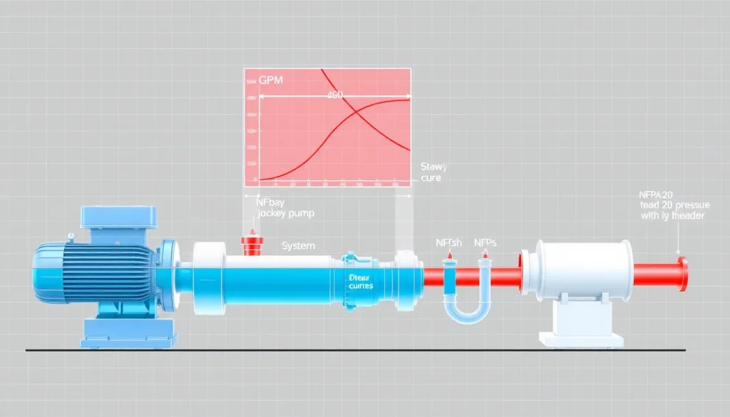
- Check curve alignment – plot the pump’s performance curve against the system curve; the operating point should lie near the peak efficiency region.
- Plan for testing – NFPA 20 requires a 30 % flow increase test at design head for acceptance.
Field adjustments such as adding a suction booster, reducing pipe length, or selecting a higher‑efficiency impeller can resolve mismatches between pump and system curves.
Common Mistakes, Limits & Safety Notes
- Mixing US and SI units in the BHP equation – always convert flow and head to the same system before applying the formula.
- Neglecting the 3‑ft NPSH margin – can cause cavitation, leading to rapid impeller erosion.
- Using the pump’s rated flow instead of the design flow from the fire‑protection hydraulic calculation – results in under‑rating.
- Oversizing the pump “just in case” – raises system pressure, increases leakage, and may violate NFPA 20 pressure‑relief device settings.
- Ignoring the 30 % acceptance test – an undersized motor may pass nominal rating but fail the surge test, jeopardizing reliability.
- Assuming constant efficiency across the entire curve – efficiency typically drops 5‑10 % at off‑design points; incorporate a safety factor.
- Failing to provide a standby power source (diesel generator or UPS) – NFPA 20 mandates an independent power source for the standby pump.
- Improper pipe sizing leading to excessive friction loss – recalculate system curve after any layout change.
Adhering to these checks preserves both life safety and equipment longevity.
FAQ
What is the difference between a standby fire pump and a jockey pump?
A standby fire pump must deliver the full design flow at the required TDH for at least 60 minutes during a fire event. A jockey pump is a small, continuously‑operating pump that maintains system pressure within a narrow band (usually ±10 psi) when the fire pump is not running.
How do I determine the required brake horsepower for a fire pump?
Calculate the hydraulic power using P = ρ g Q H, divide by the overall efficiency, and convert to horsepower (1 HP = 0.746 kW). In US units the shortcut formula BHP = (Q × H)/(3960 × η) is used.
Why does NFPA 20 require a 30 % flow increase test?
The 30 % increase test verifies that the pump‑motor assembly can handle surge conditions without excessive vibration or overheating, ensuring reliable operation during sudden demand spikes in a fire.
Can I use a positive‑displacement pump for a sprinkler system?
Yes, but only when the system demands a nearly constant flow at low pressures. Centrifugal pumps are preferred for high‑rise applications because they handle variable heads more efficiently.
What happens if the NPSH available is less than the pump’s NPSH required?
Insufficient NPSH causes cavitation, leading to impeller pitting, loss of efficiency, vibration, and potentially catastrophic pump failure during a fire event.
Do I need a separate power source for the standby fire pump?
NFPA 20 mandates an independent, reliable power source—typically a diesel generator or UPS—so the standby pump can operate even if the primary electrical supply fails.
How often must fire pumps be tested after installation?
NFPA 20 requires acceptance testing at installation, weekly operational tests, and annual performance tests, with a full acceptance test (30 % flow increase) performed at least once per year.
Is it acceptable to size a fire pump 5 % larger than the calculated rating?
A modest oversize (up to 10 %) can improve reliability, but excessive oversizing raises system pressure, may breach sprinkler design pressures, and can increase energy consumption.
Leave a Reply