
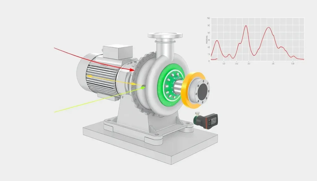
Short Answer
Key Formula / Key Facts Box
Fundamental Vibration Relation (Unbalance)
X = Fu / ks = (mu·ω²) / ks
| Symbol | Meaning | US Unit | SI Unit | Plain‑English Restatement |
|---|---|---|---|---|
| X | Steady‑state radial displacement of the shaft | in | mm | how far the shaft moves radially under vibration |
| Fu | Resultant unbalance force | lb | N | force created by mass that is not evenly distributed |
| mu | Unbalanced mass (m·e) | lb·ft | kg·m | mass times its eccentricity that creates the unbalance |
| ω | Angular speed (2π·N/60) | rad/s | rad/s | speed of rotation expressed in radians per second |
| ks | Effective shaft‑bearing stiffness | lb/in | N/m | how much the bearing resists shaft displacement |
When X exceeds design limits, vibration‑related problems such as bearing wear, seal leakage, or premature pump failure are likely.
Overview — What It Is and Why It Matters
Excessive pump vibration is the observable, often audible, oscillatory motion of a pump’s rotating assembly that exceeds the limits defined in standards such as API 610 or ISO 10816‑3. The phenomenon originates from dynamic forces that are not fully balanced by the pump’s structural stiffness and damping. In practice, engineers encounter vibration as a steady‑state sinusoidal waveform, a sudden surge, or a broadband noise. If left unchecked, vibration can cause:
- Accelerated bearing wear and premature bearing failure.
- Seal and coupling damage leading to leaks or mis‑coupling.
- Reduced hydraulic efficiency due to shaft deflection and flow‑induced instabilities.
- Increased acoustic noise, operator fatigue, and potential safety hazards.
Because pumps are often the heart of a process plant, a vibration issue can cascade into downstream equipment, causing unscheduled shutdowns and costly downtime.
The Method — Derivation and Variants
The basic vibration equation presented above derives from the classic forced‑vibration model for a rotating shaft:
m·x¨ + c·x˙ + k·x = Fu·sin(ωt)
Assuming steady‑state sinusoidal response, the displacement amplitude X becomes:
X = Fu / √[(k – m·ω²)² + (c·ω)²]
Two common engineering variants are used:
- Stiffness‑dominant (low speed) form: When ω is far below the natural frequency (ω << √(k/m)), the denominator simplifies to k, yielding the key formula X ≈ Fu/ks. This is the form most pump‑maintenance manuals employ for routine imbalance checks.
- Resonance‑aware form: Near the critical speed (ω ≈ √(k/m)), damping c becomes significant, and the full expression must be used. Engineers often apply the ISO‑defined vibration velocity limit (V = 2π·f·X) to assess proximity to resonance.
Units in the US system use pounds‑force (lb‑f) for force, inches for displacement, and pounds‑force per inch (lb‑f/in) for stiffness. The SI system uses newtons (N), millimeters (mm), and newtons per meter (N/m) respectively. The angular speed ω is identical in both systems (rad/s).
Worked Example
Example 1 – US Customary
A 10‑in centrifugal pump runs at 1 800 rpm. A vibration survey shows an unbalance mass of 0.025 lb·ft (≈0.011 kg·m) located 0.03 ft from the shaft centerline. The bearing stiffness is 1 200 lb/in. Determine the radial displacement X and compare it with the API‑610 limit of 0.020 in for this size pump.
- Convert speed to rad/s: ω = 2π·N/60 = 2π·1800/60 = 188.5 rad/s.
- Calculate unbalance force: Fu = mu·ω² = 0.025 lb·ft × (188.5)² ≈ 0.025 × 35 500 ≈ 887 lb‑f.
- Displacement: X = Fu/ks = 887 lb‑f / 1 200 lb/in ≈ 0.739 in.
- Result: X = 0.739 in ≫ 0.020 in limit → excessive vibration.
Example 2 – SI
The same pump, now expressed in metric: speed 1 800 rpm (ω = 188.5 rad/s), unbalance mass mu = 0.011 kg·m, bearing stiffness ks = 165 kN/m (≈ 1 200 lb/in). Compute X in mm.
- Fu = mu·ω² = 0.011 kg·m × (188.5)² = 0.011 × 35 500 ≈ 390 N.
- X = Fu/ks = 390 N / 165 000 N/m ≈ 0.00236 m = 2.36 mm.
- Convert to inches: 2.36 mm ÷ 25.4 ≈ 0.093 in, still above the 0.020 in limit.
Both calculations demonstrate that a modest unbalance can quickly exceed permissible vibration levels, emphasizing the need for precise balancing and stiffness verification.
Calculator
For quick on‑site calculations, use the online vibration‑amplitude calculator: http://vibrationcalc.example.com
Reference Values & Typical Ranges
- API 610 (centrifugal pumps) – Radial displacement limit: 0.010 in (≤ 125 mm impeller) to 0.030 in (≥ 250 mm impeller).
- ISO 10816‑3 – Vibration velocity for Class C machinery (large pumps): 2.5 in/s RMS (≈ 6.4 mm/s) at the bearing housing.
- Typical bearing stiffness for a 10‑in pump: 1 000–1 500 lb/in (≈ 150–210 kN/m).
- Acceptable unbalance for a rotating assembly: ≤ 0.02 lb·in (≈ 0.005 kg·mm) per 10 in of shaft diameter.
- Critical speed factor: Operate at ≤ 0.8 × first critical speed to avoid resonance.
Application Guidance
When evaluating a pump for vibration issues, follow this practical workflow:
- Baseline Survey – Record vibration velocity (mm/s) and displacement (µm) at the bearing housing, suction, and discharge flanges using a calibrated accelerometer.
- Compare to Standards – Use the limits above; if measurements exceed, proceed to root‑cause analysis.
- Identify Dominant Source – Check for shaft unbalance (run‑out test), mis‑alignment (laser alignment), bearing wear (temperature & oil analysis), cavitation (pressure pulsation), and flow‑induced forces (pump head vs. system curve).
- Corrective Action Prioritization
- Balance the impeller and rotating assembly.
- Realign motor‑pump coupling within ±0.005 in offset and ±0.1° angular error.
- Replace worn bearings and verify proper preload.
- Install flexible couplings or vibration isolators if stiffness is inadequate.
- Adjust system head to move operating point away from the pump’s critical speed.
- Verification – Repeat the vibration survey after each corrective step; document trend data for trending analysis.
Common Mistakes, Limits & Safety Notes
- Mixing US and SI units in the same calculation – leads to errors > 100 %.
- Using the stiffness‑dominant formula near resonance – underestimates displacement dramatically.
- Balancing only the impeller while ignoring the motor shaft, coupling, or accessories.
- Neglecting bearing preload; too loose a preload reduces ks and amplifies vibration.
- Relying solely on visual inspection; many vibration sources are inaudible.
- Skipping isolation of the pump from the motor during alignment checks – transferred errors mask true mis‑alignment.
- Exceeding the recommended safe exposure time to high‑velocity vibration (ISO 10816‑3 suggests < 8 h/day for Class C).
- Failing to wear appropriate PPE (hearing protection, lock‑out/tag‑out) when performing on‑site vibration measurements.
FAQ
What vibration level is considered dangerous for a centrifugal pump?
According to API 610, radial displacement above 0.020 in (0.5 mm) for a typical 10‑in pump is unsafe, and ISO 10816‑3 limits velocity to 2.5 in/s RMS for Class C equipment. Exceeding either value warrants immediate investigation.
Can cavitation cause excessive vibration?
Yes. Cavitation creates pressure pulsations that translate into high‑frequency vibration, often detected as a broadband noise on the suction side. Mitigation involves raising NPSH margin or reducing impeller speed.
How often should vibration monitoring be performed?
For critical process pumps, a baseline survey at commissioning and quarterly checks are recommended. Additional measurements should follow any major maintenance, speed change, or after detecting abnormal noise.
What is the most common source of pump vibration in the field?
Shaft unbalance is the leading cause, especially when impellers are re‑machined or when accessories are added without rebalance. It is usually identified by a consistent 1× rotational frequency component.
Is laser alignment sufficient to eliminate vibration?
Laser alignment removes angular and offset mis‑alignment, which can reduce vibration, but it does not address unbalance, bearing wear, or structural resonance. A comprehensive approach is required.
What safety precautions are needed when using handheld accelerometers?
Operators must lock‑out/tag‑out the pump, wear hearing protection, and ensure the sensor is securely mounted to avoid accidental release. Follow the manufacturer’s electrical safety guidelines.
Why does vibration increase after a bearing replacement?
Improper bearing preload or mismatched bearing stiffness can lower ks, raising displacement per the X = Fu/k relationship. Re‑checking preload and shaft run‑out usually resolves the issue.
Can flexible couplings reduce pump vibration?
Flexible couplings accommodate minor mis‑alignment and absorb shock loads, lowering transmitted vibration. However, they cannot compensate for excessive unbalance or resonance, so they are a complementary solution.

Leave a Reply