
Short Answer
Key Formula / Key Facts Box
Net Positive Suction Head (NPSH) Available:
$$NPSH_{A}=frac{P_{in}}{rho g}+frac{v^{2}}{2g}-frac{P_{v}}{rho g}-h_{f}$$
| Symbol | Meaning | US Unit | SI Unit | Plain‑English Restatement |
|---|---|---|---|---|
| Pin | Absolute pressure at pump inlet | psi | Pa | How much pressure the fluid feels before entering the pump. |
| ρ | Fluid density | lb/ft³ | kg/m³ | Mass per unit volume of the fluid. |
| g | Gravitational acceleration | 32.174 ft/s² | 9.81 m/s² | Force that pulls the fluid downwards. |
| v | Mean velocity in the suction pipe | ft/s | m/s | Speed of the fluid as it approaches the impeller. |
| Pv | Vapor pressure of the liquid at operating temperature | psi | Pa | Pressure at which the liquid would start to boil. |
| hf | Friction loss in suction line | ft | m | Pressure drop caused by pipe friction. |
Key Facts
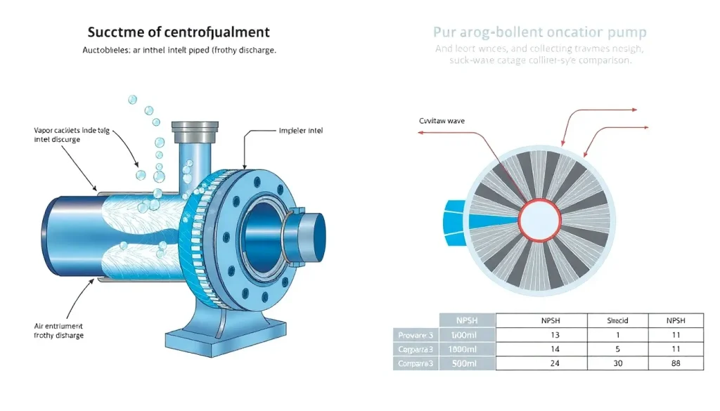
- Air entrainment introduces non‑condensable gases; cavitation involves vapor bubbles that collapse.
- Typical NPSHA for water pumps: 5–12 ft (1.5–3.6 m).
- Visible signs of cavitation: pitting, high‑frequency noise (~20–30 kHz), loss of head.
- Visible signs of air entrainment: frothy liquid, low‑frequency gurgling, erratic flow meter readings.
- Both reduce efficiency, but cavitation can cause rapid mechanical damage.
Overview — What It Is and Why It Matters
In a centrifugal pump the fluid is accelerated through the impeller and then decelerated in the diffuser. If the pressure at any point falls below the liquid’s vapor pressure, the fluid can change phase. Two distinct mechanisms produce this condition:
- Air Entrainment – non‑condensable gases (air, nitrogen, dissolved gases) are drawn into the suction line, often because the inlet is open to the atmosphere, the liquid level is low, or the suction piping is poorly vented. The gas bubbles remain gaseous throughout the pump and exit with the discharge, causing a reduction in density and a characteristic “frothy” appearance.
- Cavitation – the local pressure drops below the liquid’s vapor pressure, forming vapor cavities that collapse when they re‑enter higher‑pressure regions. The implosion creates shock waves, erosion, and a distinct high‑frequency noise.
Distinguishing the two is critical for proper troubleshooting. Mis‑identifying cavitation as air entrainment can lead to unnecessary system redesign, while ignoring cavitation can result in impeller damage, shortened service life, and costly downtime.
The Method — Derivation and Variants
The governing principle for both phenomena is the NPSH balance. Starting from Bernoulli’s equation applied between the free surface (or reservoir) and the pump inlet:
$$frac{P_{s}}{rho g}+frac{z_{s}}{g}=frac{P_{in}}{rho g}+frac{v^{2}}{2g}+frac{z_{in}}{g}+h_{f}$$
Rearranging yields the expression for NPSHA shown in the Key Facts Box. The same equation applies whether the pressure deficit is caused by vapor pressure (cavitation) or by the presence of a gas pocket (air entrainment). The distinction is made by comparing NPSHA to the pump‑provided NPSHR (required) and by inspecting the physical symptoms.
US‑Customary form (feet, psi):
$$NPSH_{A}(ft)=frac{P_{in}(psi)}{rho( lb/ft^{3})times32.174}+frac{v^{2}(ft^{2}/s^{2})}{2times32.174}-frac{P_{v}(psi)}{rhotimes32.174}-h_{f}(ft)$$
SI form (metres, pascals):
$$NPSH_{A}(m)=frac{P_{in}}{rho g}+frac{v^{2}}{2g}-frac{P_{v}}{rho g}-h_{f}$$
Constants such as g are 32.174 ft/s² (US) or 9.81 m/s² (SI). The formula is valid for incompressible liquids; for highly aerated flow a correction factor (compressibility factor Z) may be introduced, but in most industrial practice the simple form suffices for a first‑order diagnosis.
Worked Example
Example 1 – US Units (Water, 68 °F)
Given:
- Inlet absolute pressure Pin = 30 psi
- Vapor pressure of water at 68 °F = 0.43 psi
- Flow rate Q = 500 gpm, pipe ID = 4 in → velocity v = 4.9 ft/s
- Friction loss in suction line hf = 2 ft
- Fluid density ρ = 62.4 lb/ft³
- Pump NPSHR = 6 ft (from curve)
Calculate NPSHA:
$$NPSH_{A}=frac{30}{62.4times32.174}+frac{4.9^{2}}{2times32.174}-frac{0.43}{62.4times32.174}-2$$
$$=0.0150+0.372-0.00022-2 = -1.613,ft$$
Negative NPSHA indicates the suction pressure is well below vapor pressure – a classic cavitation condition. The pump will likely exhibit high‑frequency noise and impeller pitting.
Example 2 – SI Units (Water, 20 °C)
- Pin = 210 kPa
- Pv = 2.34 kPa
- Q = 0.03 m³/s, pipe ID = 0.1 m → v = 3.8 m/s
- hf = 0.6 m
- ρ = 998 kg/m³
- NPSHR = 1.8 m
Calculate:
$$NPSH_{A}=frac{210,000}{998times9.81}+frac{3.8^{2}}{2times9.81}-frac{2,340}{998times9.81}-0.6$$
$$=21.5+0.74-0.24-0.6=21.4,m$$
Since NPSHA (21 m) » NPSHR (1.8 m), cavitation is unlikely. If the operator reports frothy discharge and low suction gauge, the problem is air entrainment, not cavitation.
Calculator
Use an online NPSH calculator for quick verification: http://pumpcalcs.com/calculators/total-dynamic-head/
Reference Values & Typical Ranges
- Water at 20 °C: Vapor pressure ≈ 2.34 kPa (0.34 psi)
- Typical suction pipe friction loss: 0.5–2 ft (0.15–0.6 m) per 10 ft of pipe.
- Acceptable NPSHA margin: ≥ 1.5 × NPSHR for reliable operation.
- Air entrainment fraction that noticeably reduces pump head: > 5 % gas by volume.
- Cavitation inception number (σ) for stainless‑steel impellers: 0.2–0.4 (dimensionless).
Application Guidance
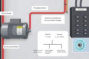
When evaluating a pump that is losing head, follow this decision tree:
- Measure suction pressure and calculate NPSHA.
- Compare with NPSHR. If NPSHA < NPSHR, cavitation is a primary suspect.
- If NPSHA ≥ NPSHR, inspect the suction line for leaks, open vents, or low liquid level – signs of air entrainment.
- Listen with a broadband acoustic sensor: 20–30 kHz → cavitation; 1–5 kHz with “gurgling” → air.
- Visually inspect discharge: frothy, milky appearance → air; clear but with pitting on impeller → cavitation.
Design recommendations:
- Keep suction pipe as short and straight as possible; install a low‑loss foot valve.
- Provide a vent or priming system to avoid drawing air.
- Maintain liquid level at least 1.5 × pipe diameter above the suction inlet.
- Select a pump with NPSHR at least 1 ft (0.3 m) below the calculated NPSHA.
Common Mistakes, Limits & Safety Notes
- Mixing units – inserting psi into a formula that expects kPa leads to erroneous NPSH values.
- Ignoring vapor pressure temperature dependence – a 10 °F rise can double water vapor pressure.
- Assuming all head loss is friction – overlook minor losses at fittings, which can be 0.5–1 ft (0.15–0.3 m) each.
- Over‑relying on pump curve NPSHR – curves are tested at specific flow; operating far off‑design changes the required NPSH.
- Failing to vent the suction line – trapped air creates a permanent gas pocket, misread as cavitation.
- Operating below the Net Positive Suction Head Margin – even a small margin deficiency can cause intermittent cavitation, leading to fatigue failure.
- Safety – cavitation can cause rapid impeller erosion, leading to imbalance and catastrophic failure. Shut down the pump immediately if high‑frequency noise and head loss appear together.
FAQ
How can I tell if the noise I hear is cavitation or air entrainment?
Cavitation typically generates a high‑pitched, metallic squeal in the 20–30 kHz range, whereas air entrainment produces a low‑frequency gurgling or bubbling sound below 5 kHz. Using a broadband acoustic sensor helps differentiate the two.
My pump is losing head but NPSH_A is higher than NPSH_R. Could it still be cavitation?
If NPSH_A exceeds NPSH_R by a comfortable margin, cavitation is unlikely. Look for signs of air entrainment such as frothy discharge, low suction gauge, or a sudden drop in liquid level.
Why does lowering the liquid level in the suction tank cause cavitation?
A lower level reduces the static head, decreasing inlet pressure. When the pressure falls below vapor pressure, vapor bubbles form, initiating cavitation.
Can I add a deaerator to eliminate air entrainment?
Yes. A deaerator removes dissolved gases and prevents large gas pockets from entering the suction line, thereby reducing air entrainment and improving NPSH_A.
Do flexible suction hoses increase the risk of cavitation?
Flexible hoses add bends and expansions, raising friction losses and creating local low‑pressure zones. This can lower NPSH_A and make cavitation more likely if the system is already marginal.
What maintenance steps should I take after a cavitation event?
Inspect the impeller for pitting or erosion, check the suction pipe for leaks, verify NPSH calculations, and consider installing a suction stabilizer or increasing inlet pressure to prevent recurrence.
Is it safe to operate a pump with NPSH_A slightly below NPSH_R for short periods?
Operating with NPSH_A just below NPSH_R can cause intermittent cavitation, which may lead to gradual impeller damage. It is not recommended for continuous service; adjust the system to increase NPSH_A before resuming full load.
How does temperature affect cavitation risk?
Higher temperature raises the liquid’s vapor pressure, reducing NPSH_A. A 10 °F (5.5 °C) increase can cut NPSH_A by up to 0.5 ft (0.15 m) for water, making cavitation more likely.
Leave a Reply