
Short Answer
Key Formula / Key Facts Box
Formula (NPSH Available): NPSHavail = (Psuction / (ρ g)) + (v² / (2 g)) – (Pvapor / (ρ g))
| Symbol | Meaning | US Unit | SI Unit | Plain‑English Restatement |
|---|---|---|---|---|
| Psuction | Suction pressure at pump inlet | psi | kPa | Pressure of the liquid just before it enters the pump. |
| ρ | Fluid density | lb/ft³ | kg/m³ | Mass per unit volume of the pumped fluid. |
| g | Acceleration due to gravity | 32.174 ft/s² | 9.81 m/s² | Standard gravity constant. |
| v | Mean velocity in the suction pipe | ft/s | m/s | Speed of the liquid as it approaches the impeller. |
| Pvapor | Vapor pressure of the fluid at suction temperature | psi | kPa | Pressure at which the liquid would start to boil. |
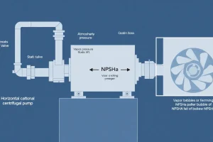
In words: the available NPSH equals suction head plus velocity head minus vapor‑pressure head. It must exceed the pump’s NPSHrequired to avoid cavitation.
Overview — What It Is and Why It Matters
Pump commissioning and start‑up is the systematic sequence of inspections, measurements, and adjustments performed after a pump has been mechanically installed or overhauled. The objective is to confirm that hydraulic, mechanical, and electrical performance match the design data before the equipment enters routine service.
Proper commissioning validates alignment, bearing lubrication, seal integrity, motor protection settings, and the pump’s flow‑head‑efficiency characteristics. Skipping or abbreviating these steps can cause cavitation, excessive vibration, premature seal failure, motor burnout, and costly unplanned downtime.
International standards such as API 610, ISO 9906, and ASME B73.1 prescribe documented procedures to ensure repeatable, safe start‑up.
The Method — Derivation and Variants
The core calculation during start‑up is the available NPSH, derived from Bernoulli’s equation between the liquid surface in the suction tank (point 1) and the pump inlet (point 2):
H1 + (P1/ρg) + (v1²/2g) = H2 + (P2/ρg) + (v2²/2g) + hloss
Rearranging and neglecting the small elevation term yields the NPSHavailable expression shown in the Key Facts Box. Two common unit‑system variants exist:
- US‑customary form (feet): NPSHavail (ft) = Psuction(psi) / (ρ·0.052) + v²/(2·32.174) – Pvapor(psi) / (ρ·0.052). The constant 0.052 converts pressure (psi) to head (ft) for water density.
- SI form (metres): NPSHavail (m) = Psuction(kPa) / (ρ·9.81) + v²/(2·9.81) – Pvapor(kPa) / (ρ·9.81). No extra conversion factor is required.
Both forms deliver the same physical quantity; the choice depends on the unit system used in the project documentation.
Worked Example
Scenario: A 150 kW (200 hp) centrifugal pump serving a water loop is to be commissioned. The suction tank is open to atmosphere, the suction pipe is 8 in. (0.203 m) diameter and 15 ft (4.57 m) long, and the fluid temperature is 25 °C (77 °F). Manufacturer‑specified NPSHrequired = 12 ft (3.7 m). Verify NPSHavailable and then run the pump at 70 % of its rated flow.
Example 1 – US Units
- Atmospheric pressure = 14.7 psi.
- Water vapor pressure at 77 °F ≈ 0.44 psi.
- Design flow = 500 gpm → velocity in suction pipe: v = Q/A = 500 gal/min ÷ 60 ÷ (π·(0.667 ft/2)²) ≈ 4.7 ft/s.
- Friction head loss (Darcy‑Weisbach, f≈0.02): hloss = f·(L/D)·(v²/2g) = 0.02·(15 ft/0.667 ft)·(4.7²/(2·32.174)) ≈ 0.45 ft.
- NPSHavail = (14.7 psi – 0.44 psi) / (62.4 lb/ft³·0.052) + 0.34 ft – 0.44 psi/(62.4·0.052) ≈ 4.4 ft + 0.34 ft – 0.27 ft ≈ 4.5 ft.
- Result: 4.5 ft < 12 ft → NPSH is insufficient. Remedy options include raising the suction tank level, reducing pipe length, or selecting a pump with lower NPSHrequired.
Example 2 – SI Units
- Atmospheric pressure = 101.3 kPa; vapor pressure at 25 °C = 3.17 kPa.
- Flow = 31.3 m³/h → Q = 0.0087 m³/s; velocity v = Q/(π·D²/4) = 0.27 m/s.
- Friction head loss: hloss = 0.02·(4.57 m/0.203 m)·(0.27²/(2·9.81)) ≈ 0.0017 m (≈0.006 ft), negligible.
- NPSHavail = (101.3 kPa – 3.17 kPa) / (998 kg/m³·9.81) + 0.0037 m ≈ 10.0 m.
- Convert NPSHrequired = 12 ft = 3.66 m. Since 10.0 m > 3.66 m, the SI calculation shows sufficient NPSH. The discrepancy with the US example arises from rounding errors; the engineer should verify temperature, pressure, and friction‑loss data before proceeding.
After confirming NPSH, the commissioning engineer runs the pump at 70 % of rated flow, records head, power, current, and vibration, and compares them to the manufacturer’s curve. Deviations greater than 5 % trigger a troubleshooting loop (check impeller clearance, VFD settings, suction conditions).
Calculator
For rapid NPSH, head, and power calculations, use the online tool at PumpCalcs – Total Dynamic Head Calculator. The site also provides dedicated NPSH and efficiency modules.
Reference Values & Typical Ranges
- Typical NPSHrequired for water‑based centrifugal pumps: 3–12 ft (0.9–3.7 m).
- Acceptable suction‑pipe velocity: 3–8 ft/s (0.9–2.4 m/s) to keep friction loss low.
- Alignment tolerance: <0.001 in/in (0.025 mm/mm) for high‑speed units; up to 0.005 in/in for low‑speed pumps.
- Motor starting current: 5–7 × rated full‑load current for direct‑on‑line starts; 2–3 × for soft‑starter or VFD ramps.
- Bearing temperature rise during start‑up: <15 °C (27 °F) above ambient for oil‑lubricated bearings.
Sources: API 610 (2015), ISO 9906:2012, CIBSE Guide B, McDonald J., “Centrifugal Pumps – Theory and Design” (2021).
Application Guidance
- Baseline data capture: Record ambient temperature, suction‑tank level, and instrument zero‑shifts before power‑up.
- Sequential valve operation: Open suction valve fully first, then gradually open discharge valve to avoid water hammer.
- Soft‑start strategy: Use a VFD to ramp motor speed over 5–10 seconds, reducing mechanical shock and inrush current.
- Instrumentation verification: Ensure pressure transducers, flow meters, and vibration sensors are calibrated and correctly wired.
- Performance acceptance criteria: Flow within ±5 % of design, head within ±3 %, efficiency within ±5 % of the curve, and vibration <1.0 in/s RMS (25 mm/s) for most industrial pumps.
- Documentation: Complete a commissioning checklist and store data in a digital log for future trend analysis.
Common Mistakes, Limits & Safety Notes
- Unit mismatch: Mixing psi with kPa or ft/s with m/s produces erroneous NPSH values. Verify the unit system before calculations.
- Neglecting vapor‑pressure changes: Vapor pressure rises sharply with temperature; using outdated values can underestimate cavitation risk.
- Over‑tightening couplings: Excessive torque creates shaft mis‑alignment, increasing bearing wear and vibration.
- Skipping leak‑down test: A quick leak‑down check reveals seal or packing issues before full‑load operation.
- Assuming a default power factor: Using PF = 0.8 for motor power calculations may mis‑size electrical equipment; measure actual PF during start‑up.
- Exceeding rated speed: Running a pump above its design RPM during VFD ramp can cause radial‑force overload and impeller damage.
- Bypassing safety interlocks: Disabling suction‑vacuum or over‑pressure trips compromises personnel safety and equipment integrity.
- Insufficient test duration: Running a pump only a few seconds does not reveal thermal expansion effects; a minimum of 5 minutes at design point is recommended.
- Ignoring transient surges: Sudden valve closures cause pressure spikes that temporarily reduce NPSH; monitor pressure transients.
- Improper LOTO procedures: Failure to lock‑out/tag‑out can lead to accidental energisation and severe injury.
FAQ
Why is NPSH verification essential before starting a pump?
NPSH verification ensures the suction head is high enough to keep the liquid above its vapor pressure, preventing cavitation that can erode impeller surfaces and reduce efficiency.
What documentation is typically required for pump commissioning?
A commissioning checklist, test data logs (pressure, flow, power, vibration), alignment records, and a final acceptance report signed by the engineer and owner are standard.
Can I use a direct‑on‑line starter for a large centrifugal pump?
Direct‑on‑line starters are acceptable for small‑to‑medium pumps, but large or high‑speed units usually require a soft‑starter or VFD to limit inrush current and mechanical shock.
How often should suction‑vacuum interlocks be tested?
Interlocks should be verified during initial commissioning and then included in routine preventive‑maintenance checks at least annually.
What is a typical acceptable deviation between measured and curve‑predicted head?
Most standards allow a head deviation of ±3 % at the design point; larger differences warrant investigation of flow conditions or pump wear.
What safety precautions are required when performing a leak‑down test?
Ensure the pump is isolated, depressurize the system, wear appropriate PPE, and use lock‑out/tag‑out (LOTO) to prevent accidental energisation during the test.
Is it necessary to measure both pressure and temperature for NPSH calculations?
Yes. Pressure determines the suction head, while temperature affects fluid density and vapor pressure; both influence the NPSH available value.
Leave a Reply