Short Answer
Key Formula / Key Facts Box
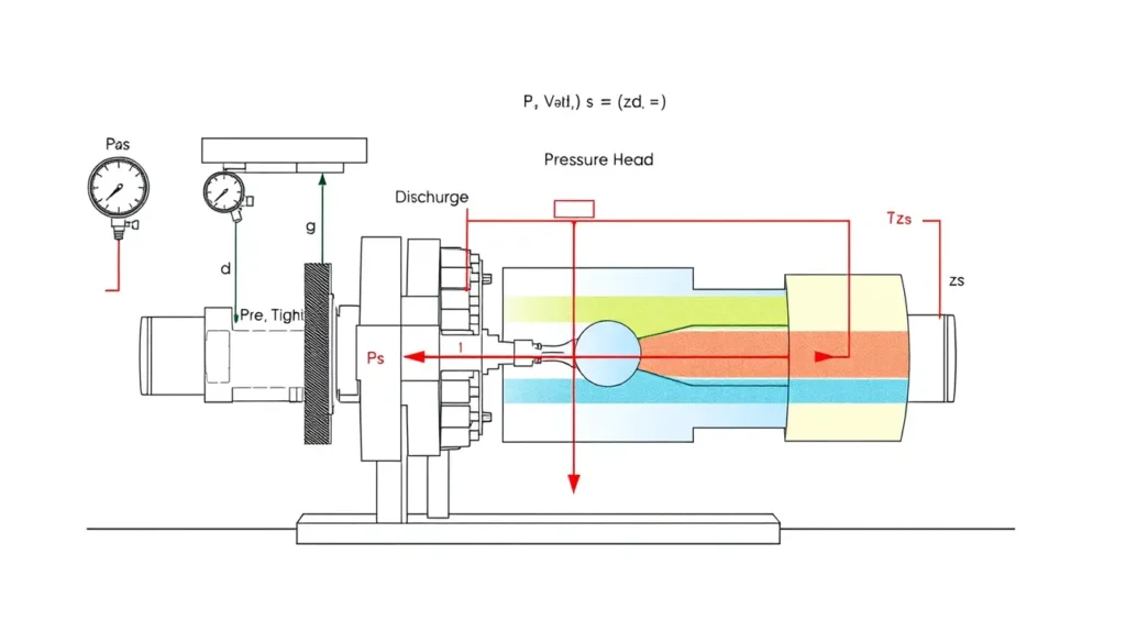
Governing formula: ΔHpump = (pd − ps)/γ + (vd2 − vs2)/(2g) + (zd − zs)
US practical form: TDH (ft) = 2.31(Pd − Ps)/SG + (Vd2 − Vs2)/64.4 + (zd − zs)
SI practical form: TDH (m) = (pd − ps)/(ρg) + (vd2 − vs2)/(2g) + (zd − zs)
| Symbol | Meaning | US unit | SI unit |
|---|---|---|---|
| ΔHpump or TDH | Head added by the pump | ft of fluid | m of fluid |
| Pd, Ps | Discharge and suction gauge pressures | psig | Pa gauge |
| γ = ρg | Specific weight of the pumped liquid | lbf/ft³ | N/m³ |
| SG | Specific gravity relative to water | unitless | unitless |
| Vd, Vs | Mean velocity at the gauge or tap locations | ft/s | m/s |
| g | Gravity constant | 32.174 ft/s² | 9.80665 m/s² |
| zd, zs | Gauge or tap center elevations from a common datum | ft | m |
Plain-English restatement: Pump head is the discharge energy per unit weight minus the suction energy per unit weight, expressed as pressure head plus velocity head plus elevation head.

Overview — What It Is and Why It Matters
Total dynamic head (TDH) is the specific energy that a pump adds to each unit weight of liquid. It is not the same as discharge pressure. A discharge gauge reports the local line pressure, which includes the suction-side pressure, elevation effects, and system backpressure. To compare a field reading with a manufacturer pump curve, the engineer must reconstruct the head the pump actually added between the suction and discharge measurement points. This article covers steady, incompressible liquid flow using gauge readings at or near the pump suction and discharge flanges.
The core idea comes from the energy equation. At any point, the liquid energy per unit weight is pressure head plus velocity head plus elevation head. The pump head is the difference between the discharge energy and suction energy. If either gauge is far from the flange, if the pipe sizes differ, or if the gauge centers are at different elevations, those contributions must be included. Ignoring them can shift the calculated head by several feet or meters, enough to make a healthy pump appear off its curve or to hide a real performance problem.
Accurate head calculation matters for commissioning, performance testing, energy audits, troubleshooting, and pump selection. An error in pressure-to-head conversion, specific gravity, or gauge elevation changes the apparent operating point. That can lead to incorrect conclusions about impeller wear, cavitation risk, system restriction, motor overload, or required impeller trim. The method is straightforward, but it demands disciplined unit handling and a clear measurement reference.
The Method — Derivation and Variants
For steady, incompressible flow, the energy per unit weight at a measurement point is E = p/γ + v²/(2g) + z. The pump head is Ed − Es, where subscripts d and s denote discharge and suction. Substituting the energy terms gives ΔHpump = (pd − ps)/γ + (vd² − vs²)/(2g) + (zd − zs). If both pressures are gauge pressures, atmospheric pressure cancels. If one reading is absolute and the other is gauge, atmospheric pressure must be added or subtracted before subtraction.
In US customary units, pressure head in feet of water is approximately 2.31 times pressure in psi at specific gravity 1.0. For another liquid, divide by specific gravity: ft = 2.31 × psi / SG. Velocity is calculated from flow and pipe inside diameter. For flow in gpm and diameter in inches, V in ft/s equals 0.4085Q/D². Velocity head in feet is V²/64.4. The elevation term uses gauge or tap center elevations measured from one common datum. If both gauge centers sit at the same elevation, the elevation term is zero.
In SI units, pressure head is p/(ρg), with pressure in pascals, density in kg/m³, and g in m/s². Velocity is Q/A, with Q in m³/s and area in m². Velocity head is v²/(2g). Elevation is the difference in gauge or tap center elevations in meters. A differential pressure transmitter can simplify the pressure term: PDIT = (pd − ps)/γ, and TDH = PDIT plus the velocity-head difference when pipe diameters differ. If gauge taps are not close to the flanges, add the friction losses between each reference point and its flange, as is done in field-assessment calculators.
Common variants are the same-size, same-elevation shortcut and the one-gauge estimate. When suction and discharge pipes have equal diameters and the gauge centers are at the same elevation, TDH is essentially the pressure-head difference. When no suction gauge exists, suction pressure can be estimated from tank level minus suction-line losses and suction velocity head for an open tank. That estimate is useful for trending but is less reliable than a direct suction measurement.
Worked Example
US example. A pump moves water with SG = 1.0 at 500 gpm. Suction pipe ID is 6 in, discharge pipe ID is 4 in, the suction gauge reads −2 psig, the discharge gauge reads 58 psig, and the gauge centers are at zs = 2.0 ft and zd = 3.5 ft.
- Pressure difference: 58 − (−2) = 60 psi. Pressure head = 60 × 2.31 / 1.0 = 138.6 ft.
- Suction velocity: Vs = 0.4085 × 500 / 6² = 5.67 ft/s. Suction velocity head = 5.67² / 64.4 = 0.50 ft.
- Discharge velocity: Vd = 0.4085 × 500 / 4² = 12.77 ft/s. Discharge velocity head = 12.77² / 64.4 = 2.53 ft.
- Velocity-head difference = 2.53 − 0.50 = 2.03 ft.
- Elevation difference = 3.5 − 2.0 = 1.5 ft.
- TDH = 138.6 + 2.03 + 1.5 = 142.1 ft at 500 gpm.
SI example. A pump moves water with ρ = 998 kg/m³ at 40 m³/h, or 0.01111 m³/s. Suction pipe ID is 0.102 m and discharge pipe ID is 0.0779 m. Suction pressure is 0.25 bar(g) = 25,000 Pa, discharge pressure is 4.50 bar(g) = 450,000 Pa, and the discharge gauge is 0.60 m above the suction gauge.
- Pressure difference = 450,000 − 25,000 = 425,000 Pa. Pressure head = 425,000 / (998 × 9.81) = 43.4 m.
- Suction area = π × 0.102² / 4 = 0.00817 m². Vs = 0.01111 / 0.00817 = 1.36 m/s.
- Discharge area = π × 0.0779² / 4 = 0.00477 m². Vd = 0.01111 / 0.00477 = 2.33 m/s.
- Velocity-head difference = (2.33² − 1.36²) / (2 × 9.81) = 0.182 m.
- TDH = 43.4 + 0.182 + 0.60 = 44.2 m at 40 m³/h.
Calculator
Use an online Total Dynamic Head calculator to check pressure-head, velocity-head, and elevation corrections. For field-assessment workflows, the MEASUR Pump Head Calculator also supports suction-tank and line-loss configurations.
Reference Values & Typical Ranges
| Item | Typical value or rule | Engineering note |
|---|---|---|
| Water pressure-to-head conversion | 1 psi ≈ 2.31 ft of water; 1 bar ≈ 10.2 m of water at SG 1.0 | Divide by SG for other liquids; use density directly in SI (HI Data Tool). |
| Gauge location | As close as practical to suction and discharge flanges | Reduces unmeasured friction and velocity change between gauge and flange (Pump Fundamentals). |
| US velocity calculation | V = 0.4085Q/D² for gpm and inches; velocity head = V²/64.4 | Use the actual pipe ID at each gauge location (Pump Fundamentals). |
| SI velocity calculation | V = Q/A; velocity head = v²/(2g) | Include velocity difference when pipe sizes differ (LogosCalc). |
| Differential transmitter | PDIT = Δp/γ; TDH = PDIT + velocity-head difference | Impulse lines must be filled and vented correctly (LogosCalc). |
| Line-loss correction | Add suction and discharge friction heads if gauges are not at the flanges | Hpump = ΔHz + ΔHp + ΔHv + Hf,s + Hf,d (MEASUR Tools Suite). |
| Suction vacuum | Negative psig is valid and common | Use a compound gauge and preserve the minus sign (Pump Fundamentals). |
| Gauge accuracy effect | 1 psi error ≈ 2.31 ft head at SG 1.0 | Use calibrated gauges; using one gauge for both readings cancels offset (Deppmann). |
| Common screening velocities | Suction about 3–10 ft/s; discharge about 8–15 ft/s | Higher values increase velocity head and friction; verify against project criteria. |
Application Guidance
In real systems, suction and discharge gauge readings move together with system changes. If the suction tank level rises, both gauges may rise, but the pump head can fall along the pump curve as flow increases. If a discharge valve closes, discharge pressure may rise while flow falls and measured TDH moves toward shutoff head. If a suction strainer fouls, suction pressure falls, flow falls, and cavitation risk rises. The calculated TDH must be paired with the simultaneous flow rate to be meaningful.
For pump selection, compare the measured TDH and flow with the catalog curve at the correct speed, impeller diameter, specific gravity, and viscosity. A field head that is lower than expected at the same flow may indicate a worn impeller, open wear ring, lower speed, or gauge error. A field head that is higher than expected may indicate a discharge restriction, incorrect piping, or a different actual flow. NPSH margin should be checked separately using suction pressure, liquid vapor pressure, and barometric pressure.
Field judgment includes using the same gauge for suction and discharge when possible, venting impulse lines, isolating gauges safely, and recording gauge elevation and pipe diameter. For high-energy pumps, use calibrated transmitters and a data logger rather than relying on a single glance at a gauge. When gauges are not at the flanges, add line losses or move the measurement points closer. Treat the result as a measured operating point, not a guaranteed exact value, and trend repeated readings to separate instrument drift from real hydraulic change.
Common Mistakes, Limits & Safety Notes
- Using discharge pressure alone as pump head. The discharge gauge includes suction pressure and system backpressure, so it is not the head added by the pump.
- Forgetting the velocity-head difference. This matters most when suction and discharge pipe diameters differ or velocities are high.
- Ignoring gauge elevation. Use gauge or tap center elevations from one common datum; do not mix pipe centerline, floor elevation, and gauge elevation.
- Mixing gauge and absolute pressure. Both readings must be in the same reference unless atmospheric pressure is added or subtracted explicitly.
- Using the wrong specific gravity or density. Hot water, slurries, and chemicals can differ significantly from water at standard conditions.
- Using a gauge reading from a location far from the flange without correcting for friction loss and velocity change between the gauge and the pump.
- Neglecting gauge calibration, air in impulse lines, blocked taps, or a compound gauge that cannot read vacuum.
- Comparing measured head with a pump curve without using the simultaneous flow, speed, impeller diameter, and viscosity correction.
- Assuming steady flow when the system is cycling, cavitating, or trapping air. Unsteady readings can scatter widely and mislead diagnosis.
- Safety: isolate and depressurize gauge lines before service, use suitable PPE for hot or hazardous liquids, avoid prolonged shutoff operation, and address cavitation or overpressure promptly.
FAQ
How do you calculate pump head from suction and discharge gauge readings?
Convert both gauge pressures to head using pressure divided by specific weight, or 2.31 times psi divided by SG for water in US units. Subtract suction head from discharge head, then add the velocity-head difference and the gauge elevation difference. Use the same flow rate and datum for both readings.
Do I need to include velocity head?
Include it whenever suction and discharge pipe sizes differ or velocities are high. Calculate V as flow divided by area, then use V squared divided by 2g. In US units, V equals 0.4085 times gpm divided by diameter squared, and velocity head equals V squared divided by 64.4. Equal diameters and low speeds may make it negligible.
What if the suction gauge reads negative?
A negative suction gauge reading is a valid vacuum and must be used with its sign. For example, minus 2 psig subtracted from 58 psig gives a 60 psi differential. Use a compound gauge rated for vacuum, vent air from impulse lines, and confirm whether the instrument reports gauge or absolute pressure.
Can I use only the discharge gauge to find pump head?
Not directly. The discharge gauge shows line pressure, not the head added by the pump. If suction pressure is unavailable, estimate it from tank level minus suction-line losses and velocity head, or use a differential transmitter. Without a valid suction reference, measured head is an estimate and should be trended rather than treated as exact.
Why does measured pump head not match the pump curve?
Check that you used the actual flow, included velocity and elevation corrections, and corrected for specific gravity. The pump may be worn, running at a different speed, cavitating, or affected by impeller clearance. Gauge error, air in lines, blocked taps, and unsteady flow also shift the calculated point. Compare at the same flow and speed.
Does gauge elevation matter?
Yes, if the suction and discharge gauge centers are at different elevations. The elevation difference is part of the energy balance. Use one common datum and enter discharge elevation minus suction elevation. If both gauges are at the same elevation, that term is zero. Do not use pipe centerline elevations unless the gauge reading refers to them.
How do I handle specific gravity?
Pressure head equals pressure divided by specific weight. For water at standard conditions in US units, one psi is about 2.31 feet of water. For a liquid with specific gravity SG, divide that water head by SG. In SI, use density directly in pressure divided by rho times g. Do not use water density for hot or chemical liquids.
What is the difference between TDH and differential pressure?
Differential pressure is just the measured pressure difference. TDH is energy per unit weight and includes pressure head, velocity-head difference, and elevation difference. If both gauges are at the same elevation and pipe sizes are equal, TDH is essentially the pressure-head difference. Otherwise, TDH and differential pressure are not numerically interchangeable.
How can I estimate suction pressure from a tank level?
For an open tank, suction pressure head is approximately tank surface elevation minus pump centerline elevation minus suction-line friction loss minus suction velocity head. Convert the result to pressure if needed. This estimate is useful when no suction gauge exists, but it is only as good as the level and loss data.

Leave a Reply