
Short Answer
Key Formula / Key Facts Box
Governing Affinity Laws (constant impeller diameter, speed change):
( frac{Q_2}{Q_1} = frac{N_2}{N_1} quad quad frac{H_2}{H_1} = left(frac{N_2}{N_1}right)^2 quad quad frac{P_2}{P_1} = left(frac{N_2}{N_1}right)^3 )
Governing Affinity Laws (constant speed, impeller diameter change):
( frac{Q_2}{Q_1} = frac{D_2}{D_1} quad quad frac{H_2}{H_1} = left(frac{D_2}{D_1}right)^2 quad quad frac{P_2}{P_1} = left(frac{D_2}{D_1}right)^3 )
| Symbol | Meaning | US Unit | SI Unit |
|---|---|---|---|
| Q | Volumetric flow rate | gpm | m³/h |
| H | Total developed head | ft | m |
| P | Absorbed power | hp | kW |
| N | Rotational speed | rpm | rpm (or rad/s) |
| D | Impeller diameter | in | mm |
Plain‑English restatement: If you double the speed (or diameter), flow doubles, head quadruples, and power increases eightfold. A 10% speed reduction cuts flow by 10%, head by 19%, and power by 27%.
Overview — What It Is and Why It Matters
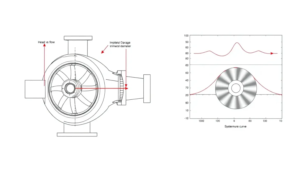
The pump affinity laws (also called pump laws or similarity laws) are a set of dimensionless scaling relationships derived from the principles of fluid dynamic similarity. They describe how the performance of a centrifugal pump—flow rate, head, and power consumption—varies with changes in rotational speed or impeller diameter, assuming the pump geometry remains similar and the system curve is purely frictional (no static head). These laws are indispensable for pump selection, variable‑speed drive (VSD) applications, impeller trimming, and troubleshooting.
Physically, the laws reflect the conservation of momentum and energy in a rotating machine. When speed increases, the impeller imparts more kinetic energy to the fluid, raising velocity proportionally (flow) and pressure quadratically (head). Power, the product of flow and head, therefore scales with the cube of speed. The same logic applies to diameter changes because a larger impeller increases tip speed and flow area linearly, while the Euler pump equation shows head depends on the square of tip speed.
In practice, the affinity laws allow engineers to predict a pump’s performance at a new speed or after impeller trimming without conducting additional tests. They are essential for energy‑efficient system design: a 20% reduction in speed can lower power demand by nearly 50%, making VSD retrofits highly attractive. However, misapplication—such as ignoring static head, efficiency shifts, or mechanical limits—can lead to undersized motors, cavitation, or inaccurate flow estimates. Understanding the laws’ assumptions and boundaries is therefore critical for safe, reliable pump operation.
The Method — Derivation and Variants
The affinity laws originate from the Buckingham π theorem and the Euler turbomachine equation. For geometrically similar pumps operating at different speeds, the dimensionless flow coefficient (Q/ND³), head coefficient (gH/N²D²), and power coefficient (P/ρN³D⁵) remain constant. When impeller diameter is the only variable, the same similarity holds if the pump casing is not modified and the impeller cutdown is moderate (typically ≤10–15% of maximum diameter).
US Customary and SI forms: The laws are independent of unit system as long as consistent units are used. The following side‑by‑side presentation clarifies common engineering practice.
| Parameter | US Customary (Q in gpm, H in ft, P in hp, N in rpm, D in in) | SI (Q in m³/h, H in m, P in kW, N in rpm, D in mm) |
|---|---|---|
| Flow | ( Q_2 = Q_1 left(frac{N_2}{N_1}right) ) or ( Q_2 = Q_1 left(frac{D_2}{D_1}right) ) | Same dimensionless form |
| Head | ( H_2 = H_1 left(frac{N_2}{N_1}right)^2 ) or ( H_2 = H_1 left(frac{D_2}{D_1}right)^2 ) | Same dimensionless form |
| Power | ( P_2 = P_1 left(frac{N_2}{N_1}right)^3 ) or ( P_2 = P_1 left(frac{D_2}{D_1}right)^3 ) | Same dimensionless form |
When each variant applies:
- Speed change (constant D): Used for VSD applications, engine‑driven pumps with throttle control, or when evaluating different motor pole speeds. The pump geometry is unchanged, so the laws hold well over a wide speed range (typically 50–120% of rated speed) provided NPSH requirements and mechanical limits are respected.
- Diameter change (constant N): Applied when impellers are trimmed to meet a specific duty point. Because the casing volute or diffuser is not altered, hydraulic similarity degrades with large cuts. Industry guidelines (ANSI/HI 14.3) recommend limiting diameter reduction to 10–15% for volute pumps and 5–10% for diffuser pumps to maintain reasonable accuracy.
- Combined speed and diameter changes: The laws can be chained: first correct for diameter, then for speed, or vice versa. The order does not affect the result because the relationships are multiplicative.
Note that the affinity laws assume constant efficiency. In reality, efficiency shifts slightly with speed (often improving at lower speeds due to reduced friction) and more noticeably with impeller trim (efficiency typically drops as diameter is reduced). For precise energy calculations, the efficiency variation should be accounted for using manufacturer data or empirical corrections.
Worked Example
Example 1 (US units, speed change): A centrifugal pump rated at 1750 rpm delivers 500 gpm at 150 ft of head, absorbing 25 hp. The system’s frictional head is dominant, and the pump will be slowed to 1450 rpm using a VFD. Find the new flow, head, and power.
Speed ratio: ( N_2/N_1 = 1450/1750 = 0.8286 ).
- New flow: ( Q_2 = 500 times 0.8286 = 414.3 text{ gpm} ).
- New head: ( H_2 = 150 times (0.8286)^2 = 150 times 0.6865 = 103.0 text{ ft} ).
- New power: ( P_2 = 25 times (0.8286)^3 = 25 times 0.5687 = 14.2 text{ hp} ).
The 17% speed reduction yields a 43% drop in power, illustrating the energy‑saving potential of VSDs.
Example 2 (SI units, impeller trim): A pump with a 260 mm impeller running at 2900 rpm provides 80 m³/h at 55 m head, drawing 18.5 kW. The impeller is trimmed to 240 mm. Estimate the new performance.
Diameter ratio: ( D_2/D_1 = 240/260 = 0.9231 ).
- New flow: ( Q_2 = 80 times 0.9231 = 73.8 text{ m³/h} ).
- New head: ( H_2 = 55 times (0.9231)^2 = 55 times 0.8521 = 46.9 text{ m} ).
- New power: ( P_2 = 18.5 times (0.9231)^3 = 18.5 times 0.7866 = 14.6 text{ kW} ).
Because the trim exceeds 10%, actual head and efficiency may be slightly lower than predicted; a 5% safety factor on power is advisable.
Calculator
For quick estimation of new duty points, use our online affinity laws calculator: Affinity Laws Calculator. Enter known flow, head, power, and the speed or diameter ratio to obtain instant results in both US and SI units.
Reference Values & Typical Ranges
- Speed adjustment range for VSDs: Typically 30–100% of rated speed. Below 30%, bearing lubrication, motor cooling, and pump efficiency may become problematic. (Source: Hydraulic Institute, ANSI/HI 9.6.3)
- Maximum impeller trim: 10–15% of maximum diameter for volute pumps; 5–10% for diffuser pumps. Beyond these limits, efficiency drops sharply and vibration may increase. (Source: ANSI/HI 14.3)
- Efficiency change with speed: Efficiency often remains within ±2% for speed changes of ±20% around BEP. At very low speeds, mechanical losses dominate and efficiency declines. (Source: ISO 9906:2012)
- Power reduction rule of thumb: A 10% speed reduction cuts power by ~27%; a 20% reduction cuts power by ~49%.
- Static head limitation: Affinity laws are accurate only when the system curve is purely frictional (H ∝ Q²). If static head exceeds 30% of total head, errors become significant; use system curve intersection instead.
- NPSH scaling: NPSH required scales approximately with the square of speed (NPSH₃ ∝ N²). A speed increase can quickly lead to cavitation if NPSH available is marginal.
Application Guidance
In real systems, the affinity laws are a starting point, not a final answer. Always overlay the new pump curve on the system curve to find the actual operating point. For systems with significant static lift, the flow change will be less than predicted because the system curve does not start at zero. In such cases, the pump head must match the sum of static head and friction head, and the intersection must be solved graphically or iteratively.
When selecting a VSD, use the affinity laws to estimate the required motor size at maximum speed and the energy savings at part load. However, account for drive losses (typically 3–5%) and motor efficiency at reduced frequency. For impeller trimming, always consult the manufacturer’s trim chart, which provides corrected performance data. If a trim chart is unavailable, limit the cut to 10% and apply a 3–5% head derate for safety.
Field adjustments often involve measuring flow and pressure before and after a speed change. If the measured head deviates from the affinity prediction, suspect a change in system resistance (e.g., fouling, valve position) or pump wear. The laws can also be used in reverse to diagnose problems: an unexpected power draw may indicate a wrong impeller diameter or speed setting.
Common Mistakes, Limits & Safety Notes
- Applying the laws to systems with high static head: The affinity laws assume a friction‑dominated system curve. If a pump lifts water 50 ft and friction is only 10 ft, a speed reduction will not reduce flow linearly; the pump may even reach shut‑off. Always check the system curve.
- Ignoring efficiency changes: Assuming constant efficiency can lead to undersized motors when speed increases, or over‑estimated savings when speed decreases. Use manufacturer data for efficiency at off‑design speeds.
- Exceeding maximum impeller trim: Trimming beyond recommended limits causes flow separation, recirculation, and sharp efficiency drop. The affinity laws become unreliable, and mechanical stresses may increase.
- Unit mismatches: Mixing gpm and m³/h, or using rpm with mm without consistent scaling, leads to gross errors. Always use dimensionless ratios.
- Neglecting NPSH requirements: A speed increase raises NPSH₃ by the square of the speed ratio. If NPSH available is not checked, cavitation damage can occur rapidly.
- Using diameter change laws for mixed‑flow or axial pumps: The affinity laws are strictly valid for centrifugal pumps with radial impellers. For mixed‑flow and axial pumps, the relationships are more complex and manufacturer‑specific.
- Over‑speeding without mechanical review: Increasing speed above the pump’s maximum rated rpm can cause impeller burst, bearing failure, or excessive vibration. Always verify with the manufacturer.
- Assuming power scales with cube of speed for the entire drive train: Motor and VFD losses may not follow the cube law; total system power savings are slightly less than pump shaft power savings.
Safety note: When modifying pump speed or impeller diameter, always re‑evaluate the maximum allowable working pressure (MAWP) of the pump casing and downstream piping. A speed increase raises shut‑off head quadratically, potentially exceeding pressure ratings and causing catastrophic failure.
FAQ
What are the pump affinity laws?
The pump affinity laws are mathematical relationships that predict how centrifugal pump flow, head, and power change when rotational speed or impeller diameter is altered. Flow changes linearly, head changes with the square, and power changes with the cube of the speed or diameter ratio, assuming constant efficiency and a friction-dominated system.
How do you calculate new flow after changing pump speed?
Multiply the original flow by the ratio of new speed to old speed: Q₂ = Q₁ × (N₂/N₁). For example, if a pump delivers 100 gpm at 1750 rpm and speed is reduced to 1450 rpm, new flow = 100 × (1450/1750) = 82.9 gpm.
Do affinity laws apply to positive displacement pumps?
No, the affinity laws are specific to rotodynamic (centrifugal and axial) pumps. Positive displacement pumps have a nearly linear flow-speed relationship but head is determined by system resistance, not pump speed, and power scales roughly linearly with speed and pressure.
What is the maximum impeller trim allowed while still using affinity laws?
For volute-type centrifugal pumps, trim up to 10–15% of maximum impeller diameter is generally acceptable. Beyond that, hydraulic similarity degrades, efficiency drops, and the affinity laws become inaccurate. Always consult the manufacturer’s trim chart.
Why does power increase so much with speed?
Power is the product of flow and head. Since flow increases linearly with speed and head increases with the square of speed, power increases with the cube of speed. Doubling speed requires eight times the power, which is why over-speeding can quickly overload a motor.
Can I use affinity laws if my system has static head?
With caution. The laws assume a purely frictional system curve (zero static head). If static head is significant, the actual flow change will be less than predicted. You must find the intersection of the new pump curve with the actual system curve for an accurate result.
How does impeller trim affect pump efficiency?
Efficiency typically decreases as impeller diameter is reduced because the clearance between impeller and casing increases, causing more internal recirculation. A 10% trim might reduce efficiency by 1–3 percentage points. Manufacturer trim data should be used for precise calculations.
What happens to NPSH required when speed increases?
NPSH required scales approximately with the square of speed. A 10% speed increase raises NPSH₃ by about 21%, which can lead to cavitation if the available NPSH margin is small. Always check NPSH when increasing pump speed.
Leave a Reply