
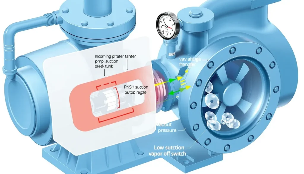
Short Answer
Key Formula / Key Facts Box
Governing minimum inlet pressure: pin,min = max[ pin,NPSH, putility,min, pcutoff ]
NPSH-based absolute limit: pin,NPSH = pv + ρg( NPSHr + M − vs2/(2g) )
Gauge limit: pin,NPSH,g = pin,NPSH − patm
US customary water check: pin,NPSH,g (psig) ≈ pv (psia) + (NPSHr + M − vs2/64.4) × SG / 2.31 − 14.7

SI water check: pin,NPSH,g (kPa) = pv + ρg( NPSHr + M − vs2/19.62 )/1000 − 101.3
Plain English: the suction pressure must leave enough absolute energy above vapor pressure to feed the pump with its required NPSH plus margin; the final minimum is the highest of the NPSH limit, the utility or code minimum, and the low-suction cutoff setting.
| Symbol | Meaning | US unit | SI unit |
|---|---|---|---|
| pin | Pressure at booster suction flange | psia or psig | kPa abs or kPa gauge |
| pv | Liquid vapor pressure at operating temperature | psia | kPa abs |
| NPSHr | Pump required net positive suction head at the design flow | ft | m |
| M | NPSH margin adopted for the application | ft | m |
| vs | Mean velocity at the suction flange | ft/s | m/s |
| ρ | Liquid density | slug/ft3 | kg/m3 |
| g | Gravitational acceleration | 32.2 ft/s2 | 9.81 m/s2 |
| patm | Local atmospheric pressure, corrected for altitude | psia | kPa abs |
Overview — What It Is and Why It Matters
In this article, minimum inlet pressure for a booster pump means the lowest pressure permitted at the booster pump suction flange while the pump operates at the design flow. It is not the minimum discharge pressure, not the pressure setpoint, and not a single fixed number copied from a catalog. The required value must satisfy three separate checks: the pump must avoid cavitation, the public main or break tank must remain within its allowed pressure range, and the low-suction cutoff must protect the system before either limit is breached. If the wording is used loosely in the field, the most useful encyclopedic scope is the suction-flange pressure check for a packaged domestic or commercial booster set.
Physically, a booster pump does not create water; it adds energy to water that is already arriving at its suction. If the inlet pressure is too low, the absolute pressure at the impeller eye can fall to the liquid vapor pressure. Vapor bubbles form, then collapse as they move into higher-pressure regions of the impeller. That is cavitation, and it produces noise, vibration, erosion, seal distress, and loss of head. The same low inlet condition can also cause the pump to lose prime, trip a low-pressure switch, or pull the municipal main below the pressure allowed by the water utility.
The engineering consequences of error are not only pump damage. A cutoff set too low can allow the main to collapse or induce backflow; a cutoff set too high can cause nuisance trips during peak demand. A calculation that uses static pressure but ignores flowing suction losses can appear satisfactory on paper and fail at the worst hour of the day. Verification must therefore be tied to the actual flow, temperature, elevation, and minimum credible supply condition.
The Method — Derivation and Variants
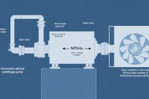
At the pump suction flange, define absolute pressure ps, liquid vapor pressure pv, and suction velocity vs. Taking the flange as the elevation datum, the available net positive suction head is:
NPSHa = (ps − pv)/γ + vs2/(2g)
where γ = ρg is the specific weight. The application is acceptable only if NPSHa ≥ NPSHr + M. Solving for absolute suction pressure gives the NPSH-based limit shown in the key box. The gauge value is obtained by subtracting local atmospheric pressure, so a negative gauge pressure can still be acceptable in a break-tank application if the absolute pressure remains above vapor pressure and the NPSH requirement is satisfied.
US customary practice usually works in psi and feet. For water near 68°F, 1 psi is approximately 2.31 ft of water, and 1 ft is approximately 0.433 psi. The constant 64.4 in the velocity-head term is 2g in ft/s2. SI practice works in kPa or Pa and metres; 2g is 19.62 m/s2. The same physics applies, but the vapor pressure and suction pressure must be expressed as absolute values before the NPSH comparison. Vapor pressure changes strongly with temperature, and atmospheric pressure changes with altitude, so neither constant should be assumed without checking the site conditions.
If the known pressure is measured upstream of the pump, such as at the building service entrance or at a tank outlet, reduce it to the suction flange before comparing with the limit. Subtract meter, backflow preventer, strainer, filter, valve, and pipe losses at the design flow, and correct for elevation between the measurement point and the flange. If the gauge is already at the suction flange while the pump runs at design flow, do not subtract those upstream losses again. This is a common source of double counting.
Worked Example
US customary example. A direct-fed domestic booster serves 250 gpm. Water is at 68°F, so pv = 0.34 psia. The pump has NPSHr = 12 ft at design flow, the adopted margin is M = 3 ft, suction velocity is 7 ft/s, and local atmospheric pressure is 14.7 psia. The utility requires at least 20 psig residual pressure at the suction, and the low-suction cutoff is to be set at 22 psig for protection. First calculate velocity head: vs2/64.4 = 49/64.4 = 0.76 ft. Then pabs,min = 0.34 + (12 + 3 − 0.76)/2.31 = 0.34 + 6.16 = 6.50 psia. In gauge terms, pg,min = 6.50 − 14.7 = −8.2 psig. The NPSH check alone therefore gives a negative gauge limit. The governing minimum is the highest of −8.2 psig, 20 psig, and 22 psig, so the enforceable minimum inlet pressure to verify is 22 psig. The pump has adequate NPSH, but the utility and cutoff requirements govern.
SI example. A break-tank booster handles water at 30°C, so pv = 4.25 kPa abs. NPSHr = 4.5 m, M = 1.0 m, suction velocity is 2.5 m/s, ρ = 996 kg/m3, g = 9.81 m/s2, and atmospheric pressure is 101.3 kPa. Velocity head = 2.52/19.62 = 0.319 m. The NPSH-based absolute pressure is pabs,min = 4.25 + 996 × 9.81 × (4.5 + 1.0 − 0.319)/1000 = 4.25 + 50.6 = 54.9 kPa abs. The gauge limit is 54.9 − 101.3 = −46.4 kPa gauge. The tank low-level switch and suction piping must therefore guarantee that the flange pressure does not fall below about 54.9 kPa abs while the pump runs at design flow. A positive gauge reading is not required for NPSH in this break-tank case, but the low-level control must still be set with an adequate margin.
Calculator
Use an online head and NPSH calculator such as pumpcalcs.com/calculators/total-dynamic-head/ to cross-check head terms, then verify NPSH with a pump-specific calculator or the manufacturer’s selection software. Enter the suction pressure at the same flow and measurement point used in the calculation.
Reference Values & Typical Ranges
| Item | Typical planning value or rule | Verification note |
|---|---|---|
| Public main minimum residual pressure | Often about 20 psi (138 kPa) at the suction under all operating conditions | Minnesota Department of Health plan-review guidance requires low-pressure control to prevent suction pressure from dropping below 20 psi and prohibits booster operation that creates negative suction pressure. |
| Normal working inlet pressure for domestic booster service | At least about 35 psi (241 kPa) is often cited as a normal working target | This is guidance, not a universal substitute for the utility agreement, local plumbing code, and pump NPSHr. |
| Low-suction cutoff | Set at or above the utility or code minimum, with a small operating margin | IPC Section 606.5.5 addresses low-pressure cutoff on booster pumps; confirm the locally adopted edition. |
| NPSH margin M | Commonly 2–5 ft (0.6–1.5 m) for ordinary water service | Use the manufacturer’s recommendation and Hydraulic Institute guidance; hot water, solvents, and high-energy pumps may require more. |
| Pressure-to-head conversion | 1 psi ≈ 2.31 ft of water at 68°F; 1 ft ≈ 0.433 psi | Correct for specific gravity and temperature when the liquid is not clean cold water. |
| Suction velocity | Commonly about 2–5 ft/s (0.6–1.5 m/s) in short suction headers | High velocity increases friction loss and velocity head; verify NPSHa at the actual flange size. |
Sources for the planning values include Grundfos inlet-pressure guidance, Minnesota Department of Health booster-station plan review, SynC domestic water booster standard, and Hydraulic Institute pump-application references. Local codes and utility tariffs always take precedence.
Application Guidance
Minimum inlet pressure behaves differently in direct-fed and break-tank systems. In a direct-fed system, the available pressure depends on the utility main, building service, meter, backflow assembly, strainers, and the demand of other users. The worst case is usually peak demand, main flushing, fire-flow drafting, or a nearby high-demand event. In a break-tank system, the available pressure depends on tank low level, tank elevation, suction-pipe losses, and the pump’s position relative to the tank. The low-level switch is part of the pressure boundary and must be verified against the NPSH calculation.
Selection follows the governing minimum, not the average reading. Confirm NPSHr at the maximum design flow and at the minimum supply condition. For variable-speed or multi-pump sets, check the staging sequence: the last pump on may operate at a different flow and suction loss than the first pump. Confirm that the low-suction cutoff protects the main without causing nuisance trips during normal peak demand. If a pressure-reducing valve, backflow preventer, or strainer is added later, recheck the suction pressure because the original calculation may no longer apply.
Field judgment should include gauge location and calibration. A gauge on the pump flange is more useful than a gauge at the service entrance, but it must be read while the pump runs at design flow. Static pressure is only a starting point. Record the minimum observed pressure, the flow at that moment, and the water temperature. If the pump is noisy, vibrating, or losing head, suspect cavitation or air entrainment before simply raising the discharge setpoint.
Common Mistakes, Limits & Safety Notes
- Using static mains pressure as available inlet pressure. Static pressure ignores flowing losses through the meter, backflow preventer, strainer, and service pipe. Verify pressure at design flow and at the worst supply condition.
- Mixing gauge and absolute pressure. Vapor pressure and NPSH calculations require absolute pressure. Convert psig to psia or kPa gauge to kPa abs before comparing with pv.
- Forgetting suction-line losses. Strainers, elbows, valves, and reducers reduce pressure at the flange. If the measured point is upstream of these items, subtract their losses at the same flow.
- Double-counting upstream losses. If the gauge is already at the suction flange while the pump runs, do not subtract the service-entrance losses again.
- Using NPSHr at the wrong flow. NPSHr usually rises with flow. Check the maximum design flow and the actual pump curve, not only the rated point.
- Setting the low-suction cutoff too low or disabling it. This can collapse the main, induce backflow, or damage the pump. Set it above the utility or code minimum and verify the setting under flow.
- Confusing minimum inlet pressure with minimum discharge pressure. The suction limit protects NPSH and the supply; the discharge setpoint delivers pressure to fixtures. They are different checks.
- Ignoring temperature and altitude. Hot water has higher vapor pressure, and high altitude lowers atmospheric pressure. Both reduce NPSHa for the same gauge reading.
- Neglecting maximum inlet pressure. Minimum pressure is the subject here, but the pump, seals, valves, and controls also have maximum pressure ratings that must be verified.
- Relying on one uncalibrated gauge. Compare the controller reading with a known-good gauge. A drifting transducer can cause hunting or a false low-suction trip.
Safety note: isolate electrical power and follow lockout/tagout before working on booster controls. Do not loosen fittings or sensors under pressure. Cavitation and low-suction operation can damage seals, erode impellers, overheat the pump, and create a public-supply contamination risk if backflow protection is inadequate.
FAQ
What is minimum inlet pressure for a booster pump?
It is the lowest pressure allowed at the pump suction flange while the pump runs at design flow. Verify the NPSH-based limit, the utility or code minimum residual pressure, and the low-suction cutoff setting. The governing minimum is the highest of those values, not simply the static mains pressure or the pump nameplate.
Is negative inlet pressure acceptable for a booster pump?
Sometimes, if the pump draws from a break tank and the NPSH calculation is satisfied. A negative gauge pressure still means positive absolute pressure. For direct-fed municipal systems, negative suction pressure is usually unacceptable because it can collapse the main, induce backflow, or trip low-pressure protection. Always convert gauge to absolute before comparing with vapor pressure.
How do I calculate minimum inlet pressure?
Use p_abs,min = p_v + ρg(NPSHr + margin − velocity head) at the suction flange, then subtract atmospheric pressure for gauge. If pressure is measured upstream, subtract suction-line, strainer, meter, and backflow losses. Compare the result with the utility minimum and low-suction cutoff; the highest value governs.
What should I verify before booster pump startup?
Confirm the suction gauge is calibrated and located at the pump flange. Record static and flowing pressure at design flow. Check strainers, valves, backflow assemblies, tank low level, and cutoff settings. Verify NPSHr at the actual flow, water temperature, altitude, and the worst-case supply condition. Compare the measured minimum with the approved submittal.
Why does my booster pump trip on low suction?
The low-suction cutoff is doing its job. Common causes are a partially closed inlet valve, clogged strainer, low tank level, utility main pressure drop during peak demand, or a cutoff set too close to normal pressure. Do not simply lower the setpoint. Find the hydraulic cause and confirm the pump still has adequate NPSH at design flow.
Does minimum inlet pressure change with flow?
Yes. NPSHr usually rises with flow, and suction losses increase roughly with the square of flow. The worst case is normally maximum design flow plus minimum supply pressure. Verify the pump curve and system curve together. A pressure reading taken at no flow can be misleading and should not be used as the only basis for a cutoff setting.
What is the difference between inlet pressure and NPSH?
Inlet pressure is a pressure at the suction flange, usually read as gauge pressure. NPSH is a head margin above vapor pressure that accounts for absolute pressure and velocity. You can have a positive inlet pressure and still fail NPSH if the water is hot or the suction losses are high. Always compare NPSHa with NPSHr plus margin.
What is a typical minimum inlet pressure for a domestic booster set?
Many public-water rules require the booster to avoid pulling the main below about 20 psi (138 kPa), and some guidance calls for normal working inlet pressure of at least 35 psi (241 kPa). Local rules, utility agreements, and the pump NPSHr can set a different value. Confirm the authority having jurisdiction and manufacturer requirements.
Leave a Reply