
Short Answer
Key Formula / Key Facts Box
Full‑Load Current (I_FL) for a three‑phase motor
[ I_{FL}=frac{P_{out}}{sqrt{3},V_{LL},PF,eta} ]
where:
| Symbol | Meaning | US Unit | SI Unit |
|---|---|---|---|
| Pout | Motor output power (shaft) | hp | kW |
| VLL | Line‑to‑line voltage | V (rms) | V (rms) |
| PF | Power factor (typically 0.85‑0.95) | — | — |
| η | Motor efficiency (often 0.90‑0.96) | — | — |
| IFL | Full‑load current (what the breaker must carry) | A | A |
Plain English: Full‑load current equals the motor’s shaft power divided by the product of voltage, power factor, efficiency and the √3 factor required for three‑phase power.
Overview — What It Is and Why It Matters
A circuit breaker protecting a pump motor is designed to open when the current exceeds a safe limit, usually 125 %–150 % of the motor’s rated full‑load current (FLC) for a short duration. Repeated trips indicate that the motor is drawing more current than the protection device expects. This condition can arise from electrical faults, supply issues, or hydraulic overloads. Ignoring the symptom can lead to premature motor insulation failure, burnt windings, or even catastrophic fire hazards, all of which increase downtime and maintenance cost.
The Method — Derivation and Variants
The basic relationship stems from the definition of electrical power:
Three‑phase apparent power: [ S = sqrt{3},V_{LL},I ]
Real power (kW) is the product of apparent power, power factor, and efficiency:
[ P_{out} = sqrt{3},V_{LL},I_{FL},PF,eta ]
Re‑arranging for current yields the formula shown in the Key Facts Box. Two practical variants are used:
- Three‑phase (most industrial pumps): ( I_{FL}=frac{P_{out}}{sqrt{3},V_{LL},PF,eta} )
- Single‑phase (small‑scale or residential centrifugal pumps): ( I_{FL}=frac{P_{out}}{V,PF,eta} )
Constants such as (sqrt{3}) (≈1.732) only appear for three‑phase. The equation assumes a balanced sinusoidal supply and that the motor is operating at its rated speed and temperature.
Worked Example
Example 1 – US customary units (three‑phase, 460 V)
- Motor name‑plate: 75 hp, 460 V, 3‑phase, PF = 0.90, η = 0.94.
- Convert horsepower to kilowatts: 75 hp × 0.7457 = 55.9 kW.
- Apply the formula:
[ I_{FL}=frac{55.9,text{kW}}{sqrt{3}times460,text{V}times0.90times0.94} ]
[ I_{FL}=frac{55,900}{1.732times460times0.846}=frac{55,900}{680}=82.2,text{A} ] - Typical breaker size: 125 % of FLC → 1.25 × 82.2 ≈ 103 A. The next standard size is 110 A.
- If the breaker trips at 90 A, the motor is drawing roughly 10 % above its FLC, suggesting overload, low voltage, or a fault.
Example 2 – SI units (three‑phase, 400 V)
- Motor name‑plate: 30 kW, 400 V, PF = 0.88, η = 0.92.
- Calculate full‑load current:
[ I_{FL}=frac{30,text{kW}}{sqrt{3}times400,text{V}times0.88times0.92}=frac{30,000}{1.732times400times0.809}=frac{30,000}{560}=53.6,text{A} ] - Breaker rating at 150 % (typical for motor‑protected breakers): 1.5 × 53.6 ≈ 80 A.
If a 63 A breaker trips, the motor may be experiencing a locked‑rotor condition or severe voltage sag.
Calculator
Use an online motor‑current calculator for quick verification: Motor Full‑Load Current Calculator
Reference Values & Typical Ranges
- Power factor for induction motors: 0.80 – 0.95 (NEMA MG‑1, 2022).
- Efficiency (IE3, premium efficiency): 0.90 – 0.96 for sizes 5 hp to 500 hp.
- Breaker trip curve (inverse‑time) – typical: 125 % of FLC for 1 hour, 150 % for 10 seconds.
- Acceptable voltage dip for most pumps: ≤ 10 % of nominal (IEEE 141‑2004).
- Locked‑rotor current (LRC) is 5 – 7 × FLC for squirrel‑cage induction motors.
Application Guidance
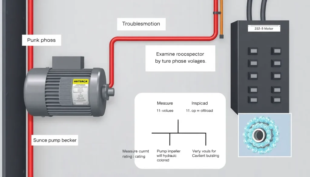
When a pump motor trips the breaker, follow this prioritized checklist:
- Verify breaker rating and type. Ensure the breaker is sized per IEC 60947‑4‑1 or NEMA MG‑1 and has an appropriate inverse‑time characteristic.
- Measure supply voltage. Use a true‑RMS meter to record line‑to‑line voltage during start‑up. A dip greater than 10 % can cause excess current.
- Check motor temperature and ventilation. Overheated windings increase resistance, raising current draw.
- Inspect pump hydraulic condition. Cavitation, closed discharge, or a blocked suction line raises torque demand.
- Examine motor wiring and connections. Loose terminals add resistance; corroded contacts can cause arcing and nuisance trips.
- Run a no‑load test. If the motor still exceeds 110 % of FLC without the pump, the issue is electrical rather than hydraulic.
- Consider motor protection settings. Adjust the overload relay or replace a thermal‑magnetic breaker with a motor‑protective circuit breaker (MPCB) that includes locked‑rotor protection.
Common Mistakes, Limits & Safety Notes
- Using name‑plate horsepower directly in the formula. Forgetting to convert hp to kW leads to a 0.746× error.
- Ignoring power factor and efficiency. Assuming PF = 1 or η = 1 underestimates current by up to 20 %.
- Mixing US and SI units. Voltage in V, power in hp, and current in A creates inconsistent results.
- Selecting a breaker that is too large. Oversized breakers may not trip before motor insulation fails.
- Neglecting locked‑rotor current. Starting the pump against a closed discharge can push current to 6 × FLC, instantly tripping a breaker not rated for LRC.
- Assuming a perfectly balanced three‑phase supply. Unbalanced voltages increase neutral current and can cause one phase to overheat.
- Bypassing the breaker for “testing”. This removes protection and violates OSHA 1910.331‑333.
- Exceeding the motor’s thermal class. Continuous operation above 125 % of FLC without proper cooling violates IEC 60034‑30‑1.
FAQ
Why does my pump motor trip the breaker only during start‑up?
During start‑up the motor draws a high inrush (locked‑rotor) current. If the supply voltage is low or the breaker is not rated for LRC, the instantaneous current can exceed the breaker’s short‑circuit rating, causing an immediate trip.
Can a voltage dip of 5 % really cause a breaker trip?
A 5 % dip alone usually won’t trip a properly sized breaker, but it reduces the motor’s magnetic flux, causing it to draw more current to develop the same torque. Combined with a high load, the current can rise above the breaker’s 125 % threshold.
What is the difference between a thermal overload relay and a motor‑protective circuit breaker?
A thermal overload relay provides only overload protection and responds slowly (seconds to minutes). An MPCB adds short‑circuit and locked‑rotor protection with an inverse‑time characteristic, offering faster and more comprehensive protection for motor applications.
My pump runs fine, but the breaker trips after a few minutes. What should I inspect?
Check for gradual heating of the motor windings, clogged pump suction, or a partially closed discharge valve. Any increase in hydraulic resistance raises torque demand, which can cause the motor to exceed its rated current after a warm‑up period.
Is it safe to replace a 150 A breaker with a 200 A unit to stop trips?
No. Upsizing the breaker removes the protective margin and allows the motor to operate beyond its thermal limits, increasing the risk of insulation failure or fire. The correct approach is to identify why the motor exceeds its FLC and address the root cause.
How can I tell if the breaker itself is faulty?
Measure the breaker’s trip current with a calibrated test set or a calibrated overload relay. If the breaker trips at a current below its rated setting, replace it. Also inspect contacts for pitting or welding, which can cause nuisance trips.
Do I need to consider harmonic distortion when troubleshooting trips?
Severe voltage harmonics (especially 5th and 7th) can increase RMS current and heating in induction motors. If the facility has large variable‑frequency drives (VFDs), verify that motor‑rated breakers are compatible with the distorted waveform.
What role does power factor correction play in preventing trips?
A low PF increases the apparent power for a given real power, raising line current. Installing PF correction capacitors reduces line current, keeping it within the breaker’s rating, especially during light‑load operation.

Leave a Reply