
Short Answer
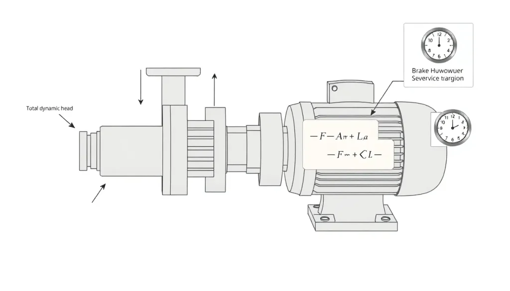
Key Formula / Key Facts Box
Brake Horsepower (BHP) / Motor Power (kW)
| Symbol | Meaning | US Unit | SI Unit | Plain‑English Restatement |
|---|---|---|---|---|
| P | Total hydraulic power required | ft·lb/s | W | Energy per second the pump needs |
| Q | Volumetric flow rate | gpm | m³/s | How much fluid moves per minute/second |
| ΔH | Total dynamic head | ft | m | Height the fluid is lifted, including losses |
| ρ | Fluid density | lbm/ft³ | kg/m³ | Mass per unit volume |
| g | Acceleration due to gravity | 32.174 ft/s² | 9.81 m/s² | Standard gravity constant |
| η_p | Pump hydraulic efficiency | – | – | How well the pump converts input power to head |
| η_m | Motor mechanical/electrical efficiency | – | – | How efficiently the motor turns electrical power into shaft power |
| SF | Service factor (safety factor) | – | – | Multiplier to accommodate overloads and start‑up peaks |
US Customary Form (Brake HP):
BHP = (Q × ΔH × ρ × g) / (η_total × 550)
SI Form (kW):
kW = (Q × ΔH × ρ × g) / η_total
Where η_total = η_p × η_m and the final motor rating = BHP × SF (or kW × SF).
Overview — What It Is and Why It Matters
Sizing a pump motor is the process of determining the minimum motor rating that will reliably drive a pump at its required flow and head while surviving start‑up transients, occasional overloads, and variations in fluid properties. The motor’s horsepower (or kilowatt) rating, combined with a service factor and a safety margin, ensures the pump operates within its efficiency envelope and that the motor does not overheat, which could lead to premature bearing wear, insulation failure, or catastrophic shutdown.
Inadequate sizing results in reduced flow, excessive temperature rise, and shortened equipment life. Oversizing, while seemingly safe, increases capital cost, reduces system efficiency, and may cause poor pump control (e.g., cavitation due to low suction pressure).
The Method — Derivation and Variants
The starting point is the hydraulic power needed by the pump:
P_h = ρ × g × Q × ΔH
where ρ·g converts the head into a pressure, and the product with Q gives power. Because real pumps and motors are not 100 % efficient, we divide by the overall efficiency:
P_input = P_h / (η_p × η_m)
In US customary units, power in foot‑pounds per second is converted to brake horsepower by dividing by 550 (the number of ft·lb/s in one HP). In SI, the result is already in watts, which we convert to kilowatts by dividing by 1 000.
US Customary Variant (Brake HP):
BHP = (Q[gpm] × ΔH[ft] × ρ[lbm/ft³] × g[ft/s²]) / (η_total × 550)
SI Variant (Kilowatts):
kW = (Q[m³/s] × ΔH[m] × ρ[kg/m³] × g[m/s²]) / η_total
After the base power is known, a service factor (SF) – typically 1.15 to 1.30 for continuous duty – is applied to accommodate start‑up currents, temperature excursions, and occasional overloads. Finally, a safety margin (often an additional 5‑10 %) can be added for long‑term reliability.
Worked Example
Example 1 – US Customary
- Flow required: 2 500 gpm
- Total dynamic head: 120 ft
- Fluid: water at 68 °F (ρ = 62.4 lbm/ft³)
- Pump efficiency: η_p = 0.78
- Motor efficiency: η_m = 0.90
- Service factor: SF = 1.20
- Safety margin: 5 %
Step 1 – Compute total efficiency: η_total = 0.78 × 0.90 = 0.702.
Step 2 – Hydraulic power (ft·lb/s):
P_h = 62.4 × 32.174 × 2 500 × 120 = 60 112 800 ft·lb/s
Step 3 – Brake HP before factors:
BHP_base = 60 112 800 / (0.702 × 550) ≈ 155.8 HP
Step 4 – Apply service factor and safety margin:
BHP_design = 155.8 × 1.20 × 1.05 ≈ 196 HP
Result: Select a NEMA Premium motor rated at 200 HP (or the next standard size up).
Example 2 – SI
- Flow required: 0.158 m³/s (≈ 3 300 gpm)
- Total dynamic head: 36 m
- Fluid: oil, ρ = 870 kg/m³
- Pump efficiency: η_p = 0.82
- Motor efficiency: η_m = 0.93
- Service factor: SF = 1.15
- Safety margin: 8 %
Step 1 – η_total = 0.82 × 0.93 = 0.7626.
Step 2 – Hydraulic power (W):
P_h = 870 × 9.81 × 0.158 × 36 ≈ 4 855 W
Step 3 – Motor power before factors:
kW_base = 4 855 / 0.7626 ≈ 6.36 kW
Step 4 – Apply factors:
kW_design = 6.36 × 1.15 × 1.08 ≈ 7.90 kW
Result: Choose a standard IEC 5 kW motor with a 10 kW rating or a 7.5 kW motor with a suitable overload rating.
Calculator
Use an online pump‑motor sizing tool for quick verification: Pump Power Calculator.
Reference Values & Typical Ranges
- Pump hydraulic efficiency (centrifugal, water): 70‑85 % (ISO 9906).
- Motor efficiency (NEMA Premium): 90‑95 % (IEEE 841).
- Service factor for continuous duty: 1.15‑1.30 (ANSI/IEEE).
- Safety margin commonly applied: 5‑10 % above the SF‑adjusted rating.
- Standard motor size increments (US): 5, 7.5, 10, 15, 20, 30, 40, 55, 75, 100, 150, 200 HP.
- Standard motor size increments (IEC): 0.75 kW, 1.1 kW, 1.5 kW, 2.2 kW, 3.0 kW, 4.0 kW, 5.5 kW, 7.5 kW, 11 kW, 15 kW, 22 kW, 30 kW, 45 kW, 60 kW, 75 kW, 90 kW, 110 kW.
Application Guidance
When integrating the motor into a system, consider the following:
- Start‑up current: Motors can draw 5‑7× rated current for a few seconds. Verify that the upstream electrical supply and protective devices can handle this.
- Temperature ambient: For installations above 40 °C, increase the safety margin or select a motor with a higher NEMA temperature class.
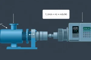
- Variable‑frequency drive (VFD): If a VFD will be used, the motor rating can be reduced by up to 10 % because VFDs limit inrush and allow soft‑starting.
- Fluid property changes: Viscous liquids or temperature‑dependent density require recalculating ρ and η_p for worst‑case conditions.
- Mechanical coupling: Verify that the shaft speed (rpm) from the motor matches the pump’s best‑efficiency point (BEP). If not, consider a gear reducer and adjust the motor rating accordingly.
Common Mistakes, Limits & Safety Notes
- Using the wrong unit system – mixing gpm with m and ft with m³/s leads to errors of >30 %.
- Neglecting pump efficiency – assuming η_p = 1 inflates the motor size dramatically.
- Omitting the motor’s own losses – η_m must be included; otherwise the motor will overheat.
- Applying the service factor twice – some manufacturers already embed a safety factor in their ratings.
- Ignoring ambient temperature limits – a motor rated for 40 °C will overheat in a 55 °C enclosure.
- Selecting a motor that is too far above the required size – can cause poor load sharing, higher operating costs, and increased bearing wear.
- For highly viscous fluids, the standard efficiency curves are invalid; a specialty pump curve must be used.
- Exceeding the motor’s NEMA/IEC duty class (e.g., running a continuous‑duty motor at intermittent overload without proper cooling).
FAQ
Why can’t I just pick the next larger motor size without a safety margin?
Skipping a safety margin may seem convenient, but it ignores start‑up currents, temperature rise, and occasional overloads. Without the margin, the motor can overheat, reducing lifespan and potentially violating warranty terms.
Do I need to apply a service factor if my motor already has a NEMA Premium rating?
NEMA Premium motors are rated for continuous duty at full load, but they do not inherently include a service factor for overload or start‑up peaks. Adding a typical SF of 1.15‑1.30 is still recommended unless the manufacturer specifies otherwise.
How does fluid viscosity affect motor sizing?
Higher viscosity increases hydraulic losses, lowering pump efficiency (η_p). Re‑calculate η_p using the pump’s viscosity‑corrected curve; the resulting lower efficiency raises the required motor horsepower.
Can a VFD reduce the required motor horsepower rating?
Yes. A VFD limits inrush current and allows soft‑starting, often permitting a 5‑10 % reduction in the motor’s name‑plate rating while still meeting performance and overload requirements.
What is the difference between brake horsepower and shaft horsepower?
Brake horsepower (BHP) is the power measured at the motor’s output shaft before any mechanical losses (e.g., couplings). Shaft horsepower is essentially the same as BHP for direct‑coupled pumps; the term “shaft horsepower” is more common in the US power industry.
Is it acceptable to use the motor’s rated efficiency in the calculation instead of the actual operating efficiency?
No. Rated efficiency is a maximum value under ideal conditions. Use the motor’s actual efficiency at the expected operating point, which is often slightly lower, to avoid under‑sizing.
How do ambient temperature variations influence motor selection?
Higher ambient temperatures reduce a motor’s ability to dissipate heat. When the installation temperature exceeds the motor’s rated ambient limit, increase the safety margin or select a motor with a higher temperature class (e.g., NEMA TEFC with 55 °C rating).
What if my pump operates at variable flow rates?
Size the motor for the maximum expected flow and head combination, then consider a VFD to adjust speed efficiently. The safety factor should still be based on the worst‑case (peak) condition.
Leave a Reply