
Short Answer
Key Formula / Key Facts Box
| Symbol | Meaning | US Unit | SI Unit | Plain‑English Restatement |
|---|---|---|---|---|
| Pmax | Maximum differential pressure the magnetic coupling can sustain | psi | kPa | The highest pressure the pump can handle before the magnetic field slips. |
| ηmag | Magnetic coupling efficiency (torque transmission) | % | % | How much of the motor torque actually reaches the impeller. |
| Δs | Coupling slip (difference between driver and driven speeds) | rpm | rpm | Speed loss caused by magnetic slip under load. |
| Q | Volumetric flow rate | gpm | m³/h | Amount of fluid moved per unit time. |
| ηhyd | Pump hydraulic efficiency | % | % | Ratio of hydraulic power to mechanical input. |
| τmag | Transmitted torque | lb·ft | N·m | Rotational force passed through the magnetic coupling. |
Overview — What It Is and Why It Matters
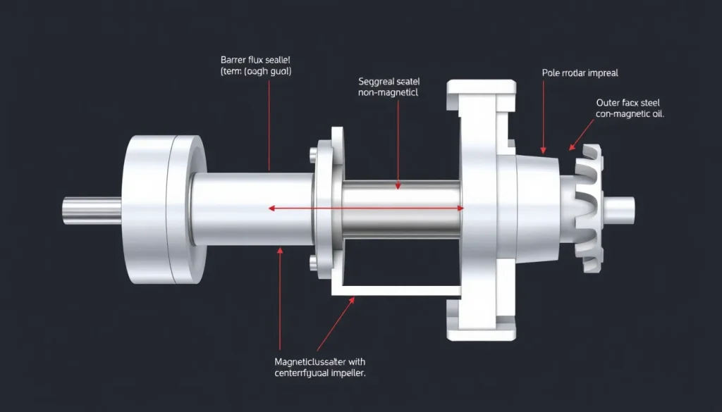
A magnetic drive pump, often called a sealless pump, uses a non‑contact magnetic coupling to transfer torque from the motor to the impeller. The coupling consists of an inner rotor (attached to the motor shaft) and an outer rotor (attached to the pump shaft) separated by a hermetically sealed barrier—usually a stainless‑steel or ceramic housing filled with a non‑magnetic fluid. Because there is no mechanical seal, the pumped fluid never contacts the external environment, eliminating leak paths for hazardous, toxic, or high‑purity liquids.
From a design perspective the magnetic coupling introduces two new design variables: magnetic slip (Δs) and coupling efficiency (ηmag). Failure to account for these can cause excessive motor heating, premature bearing wear, or catastrophic coupling failure. Consequently, accurate sizing of the magnetic coupling is as critical as selecting the impeller geometry.
The Method — Derivation and Variants
The torque transmitted by a magnetic coupling can be derived from the energy stored in the magnetic field. For a simple cylindrical permanent‑magnet coupling, the average torque is:
τmag = (π·B2·A·R)/(2·μ0)·ηmag
where:
- B = flux density in the air gap (Tesla)
- A = effective pole face area (m²)
- R = mean radius of the pole (m)
- μ0 = permeability of free space (4π×10⁻⁷ H/m)
- ηmag = efficiency factor accounting for leakage flux and hysteresis losses.
In US customary units the same expression becomes:
τmag(lb·ft) = (π·B²·A·R)/(2·μ0)·ηmag·(1/1.3558)
Two common variants exist:
- Permanent‑magnet coupling – uses rare‑earth (NdFeB) or ferrite magnets; excels in high‑efficiency, low‑slip applications up to ~10 000 psi.
- Electromagnetic (induction) coupling – powered coils create a rotating field; allows variable torque and “soft‑start” but incurs higher heat loss.
Selection of the variant depends on the required pressure, temperature, and chemical compatibility of the barrier fluid.
Worked Example
Example 1 – US Units
Design a magnetic drive pump to deliver 500 gpm of a 150 °F water‑glycol mixture at a differential pressure of 1 200 psi. The motor provides 150 hp at 1 800 rpm. Assume a permanent‑magnet coupling with B = 0.8 T, pole area A = 0.025 ft², mean radius R = 0.15 ft, and ηmag = 0.92.
- Convert flow to hydraulic power: Phyd = (Q·ΔP)/(3960) = (500 gpm·1200 psi)/3960 ≈ 151.5 hp.
- Assume overall pump efficiency ηoverall = ηhyd·ηmag ≈ 0.78·0.92 = 0.718. Required motor power = Phyd/ηoverall ≈ 211 hp (exceeds available 150 hp → redesign).
- Compute torque needed at the impeller: τimp = (HP·5252)/N = (151.5·5252)/1800 ≈ 442 lb·ft.
- Calculate magnetic torque capacity using the formula above: τmag = (π·B²·A·R)/(2·μ₀)·ηmag. Substituting B=0.8 T (≈8000 gauss), A=0.025 ft² (≈2.32×10⁻⁴ m²), R=0.15 ft (≈0.0457 m), μ₀=4π×10⁻⁷ H/m gives τmag ≈ 480 lb·ft.
- Since τmag > τimp, the coupling can transmit the required torque, but the motor is undersized. Increase motor power or reduce flow/pressure.
Example 2 – SI Units
Design a sealless pump for 12 m³/h of 60 °C methanol at 8 bar. Motor rating 30 kW at 1 500 rpm. Coupling data: B = 0.9 T, A = 0.00035 m², R = 0.05 m, ηmag = 0.94.
- Hydraulic power: Phyd = Q·ΔP = (12 m³/h ÷ 3600 s)·8 × 10⁵ Pa ≈ 2.67 kW.
- Assume ηhyd = 0.80. Motor power needed = Phyd/ (ηhyd·ηmag) ≈ 2.67 kW / (0.80·0.94) ≈ 3.55 kW < 30 kW, so motor is adequate.
- Impeller torque: τimp = (P·60)/(2π·N) = (3.55 kW·60)/(2π·1500 rpm) ≈ 22.6 N·m.
- Magnetic torque capacity: τmag = (π·B²·A·R)/(2·μ₀)·ηmag = (π·0.9²·0.00035·0.05)/(2·4π×10⁻⁷)·0.94 ≈ 31 N·m.
- τmag exceeds τimp, confirming safe operation.
Calculator
For rapid sizing of magnetic coupling torque and slip, use the online tool: Magnetic Drive Slip Calculator.
Reference Values & Typical Ranges
- Maximum differential pressure: 0.5 – 12 000 psi (3.5 kPa – 83 MPa) depending on magnet grade.
- Coupling efficiency: 85 % – 97 % for permanent‑magnet designs.
- Typical slip at full load: 0.1 % – 2 % of shaft speed.
- Seal‑free life: 10 000 – 100 000 h, governed by bearing wear and barrier‑fluid degradation.
- Operating temperature range of barrier fluid: –20 °C – 250 °C (–4 °F – 482 °F).
Application Guidance
When specifying a magnetic drive pump, follow these steps:
- Identify the most aggressive fluid property (corrosiveness, toxicity, vapor pressure).
- Determine the required differential pressure and flow rate.
- Select a coupling material compatible with barrier fluid (e.g., PTFE, fluorinated oil).
- Size the magnetic coupling using the torque equation; add a 15 % safety margin.
- Confirm that motor power, bearing rating, and cooling capacity exceed the calculated values.
- Consider a double‑magnetic barrier for ultra‑high‑purity or explosive atmospheres.
Common Mistakes, Limits & Safety Notes
- Ignoring magnetic slip – Designers often assume zero slip; at high pressure the slip can rise to >1 % and cause motor overspeed.
- Mixing US and SI units – The torque formula contains μ₀; using inconsistent units yields errors of >100 %.
- Undersizing the barrier fluid pump – The barrier fluid loop must be capable of removing the heat generated by eddy‑current losses.
- Exceeding pressure rating – Operating above the coupling’s rated pressure can cause demagnetization or catastrophic failure.
- Neglecting bearing lubrication – Sealless pumps still rely on bearing oil; inadequate lubrication leads to premature bearing wear.
- Improper thermal expansion allowance – The magnetic coupling housing expands with temperature; clearance must accommodate this to avoid binding.
FAQ
Why would I choose a magnetic drive pump over a mechanically sealed pump?
A magnetic drive pump eliminates shaft seals, so there is no leakage path for hazardous or high‑purity fluids. This reduces environmental risk, maintenance costs, and eliminates the need for seal‑cooling systems.
Can magnetic drive pumps handle abrasive fluids?
Yes, if the barrier fluid and coupling materials are selected for abrasion resistance. However, high‑abrasive loads increase bearing wear, so regular monitoring is essential.
What is the typical efficiency penalty for a magnetic coupling?
Magnetic couplings usually operate at 85 %–97 % efficiency. The small loss appears as additional motor heat and is accounted for in the overall pump efficiency calculation.
How does temperature affect the magnetic coupling’s capacity?
Elevated temperature can reduce the magnet’s remanence, lowering the maximum transmissible torque. Most permanent‑magnet couplings are rated up to 200 °C; beyond that an electromagnetic coupling may be required.
Do magnetic drive pumps require special motor protection?
Because slip can cause motor overspeed, a motor overload or slip‑monitoring relay is recommended. Additionally, a soft‑starter can limit inrush currents during start‑up.
Is a barrier fluid pump needed for every magnetic drive system?
Yes, the barrier fluid must be circulated to remove heat generated by eddy currents and to maintain viscosity for proper sealing. The pump is typically sized to handle 1.5–2 times the heat load of the main pump.
Can I retrofit a magnetic drive onto an existing mechanically sealed pump?
Retrofit is possible if the pump housing can accommodate the sealed magnetic coupling housing and if the shaft geometry matches. Engineering review of bearing alignment and motor coupling is required.
What safety standards apply to magnetic drive pumps handling explosive gases?
They must comply with ATEX/IECEx directives for equipment in explosive atmospheres, and the barrier fluid system must be classified as intrinsically safe or flame‑proof.
Leave a Reply